Newsletter Subscribe
Enter your email address below and subscribe to our newsletter

HVAC made simple

Installing a 24,000 BTU mini split is more involved than mounting an indoor unit, placing a condenser outside, and connecting the two. A 24K system represents approximately 2 tons of nominal heating and cooling capacity, and getting good performance from that equipment depends on decisions made well before installation day. Sizing, indoor-unit placement, outdoor-unit location, electrical requirements, refrigerant piping, condensate drainage, evacuation, commissioning, and manufacturer requirements all need to work together.
When I evaluate a 24K installation, I start with a simple principle: the equipment should follow the building design, not the other way around. I would first establish the heating and cooling load, decide where that capacity needs to be delivered, and then select the exact equipment. Only after those decisions would I finalize the electrical circuit, line-set route, mounting locations, and installation details.
That sequence matters because two 24K mini splits can have substantially different installation requirements. One may use different line-set diameters, electrical protection, refrigerant, allowable piping lengths, or low-temperature operating limits than another. The model number—not merely the 24,000 BTU label—ultimately determines many of the installation specifications.

Before installing a 24K mini split, I would confirm that approximately two tons of capacity actually makes sense for the intended space. Square footage can provide an early planning reference, but it should not be treated as a substitute for a heating and cooling load calculation.
The Air Conditioning Contractors of America describes Manual J as the nationally recognized methodology for calculating residential heating and cooling loads. The calculation considers factors such as climate, insulation, windows, infiltration, orientation, construction characteristics, and other conditions that affect the building load. ACCA Manual J
This is particularly important with mini splits because an inverter-driven system can modulate its output, but modulation does not make sizing irrelevant. Every system has an operating range. If a 24K unit is substantially oversized for the actual load, even its minimum output may be more capacity than the space needs during mild weather. If it is undersized, it may struggle during design conditions.
I would therefore treat “24K” as the result of the sizing process rather than the starting assumption.
Correct total capacity does not automatically mean correct air distribution. A wall-mounted mini split delivers conditioned air from one location, unlike a ducted system that distributes air through supply registers around the building.
One 24K indoor head can work very well in a large open living area, loft, studio, finished basement, garage, workshop, or similarly open thermal zone. The situation changes when the same square footage is divided among bedrooms, offices, hallways, bathrooms, or other enclosed areas.
Walls and closed doors restrict airflow. A 24K head in a living room cannot be expected to push conditioned air reliably around several corners and into closed bedrooms simply because its total capacity is large enough for the combined square footage.
Before installation, I would therefore separate two questions: Does the system have enough capacity, and can that capacity reach the areas that need it? If the second answer is no, two smaller systems or a properly designed multi-zone arrangement may be more appropriate.

Once a single 24K indoor unit has been selected, its exact location deserves careful planning. I want the discharge air to have a clear path across the primary occupied area rather than immediately encountering a tall cabinet, wall, beam, curtain, or other obstruction.
The installation manual will specify required clearances around the indoor unit. Those clearances are important for airflow, service access, filter removal, and proper installation.
I would also think about what is behind and below the indoor unit. Refrigerant piping, wiring, and the condensate drain typically need to leave the unit and travel toward the exterior or another planned route. Choosing a visually attractive location without considering those connections can produce an unnecessarily complicated installation.
Bedroom installations deserve particular attention to airflow direction and sound, while living areas need consideration of furniture placement and occupancy. In workshops or garages, the unit should also be protected from likely physical damage and located where its filters remain reasonably accessible.

During cooling and dehumidification, moisture condenses on the indoor coil and must be drained away. Condensate management should therefore be planned at the same time as indoor-unit placement.
Where possible and permitted by the equipment design, gravity drainage provides a straightforward approach. The drain needs an appropriate route and slope according to the manufacturer’s instructions so water does not back up into the indoor unit.
A poor drain installation can lead to dripping, staining, odors, water damage, or biological growth. The drain termination also needs to be appropriate for the building and local requirements.
If gravity drainage is impossible, a condensate pump may be needed. Pumps introduce another component that requires power, maintenance, and eventual service, so I would not add one unnecessarily when a good gravity route is available.
Before the installation is considered complete, I would want the condensate system tested with water rather than simply assuming it drains because the tubing appears correctly installed.
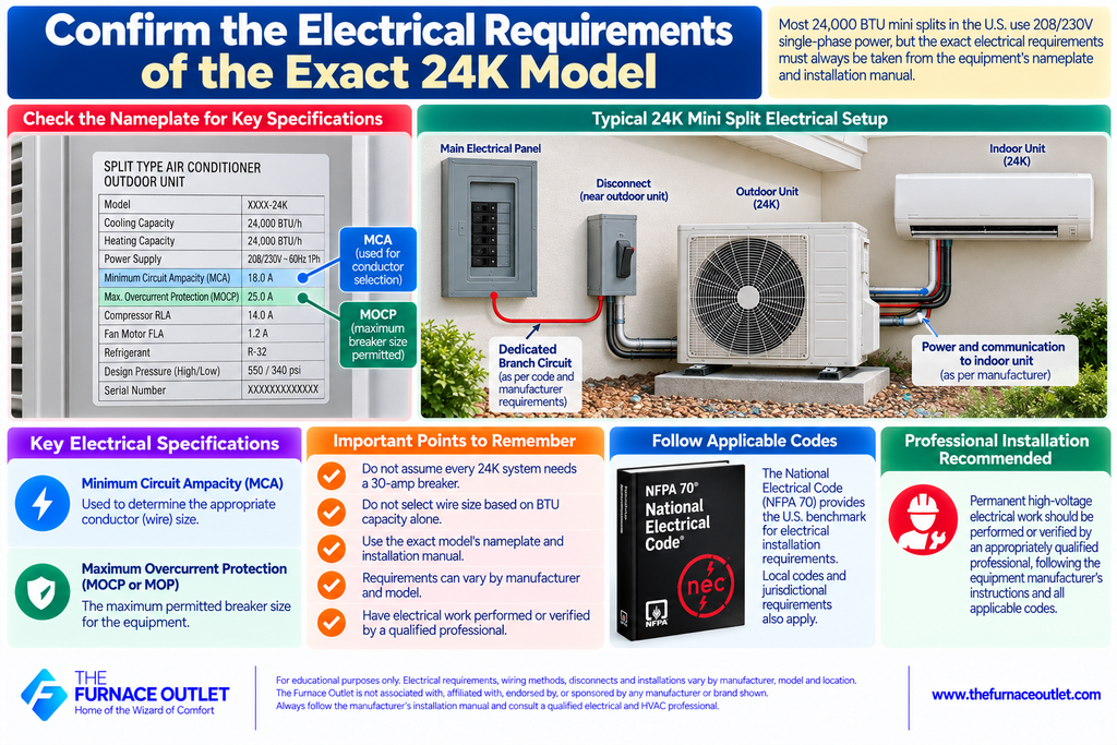
Many U.S.-market 24,000 BTU mini splits operate on 208/230V single-phase power, but that should not be converted into a universal rule about breaker or wire size.
The two electrical specifications I look for are Minimum Circuit Ampacity (MCA) and Maximum Overcurrent Protection (MOCP or MOP). MCA is relevant to conductor selection, while MOCP establishes the maximum permitted overcurrent-protection value for the equipment.
A 24K system should not automatically receive a 30-amp breaker merely because another 24K model uses one. Likewise, wire size should not be selected from BTU capacity alone.
Many installations use a dedicated branch circuit running from the electrical panel to a disconnect near the outdoor unit. Depending on the equipment design, the outdoor unit may then supply power and communication to the indoor unit through manufacturer-specified interconnecting wiring.
The National Electrical Code, NFPA 70, provides the U.S. benchmark for electrical installation requirements, while the locally adopted edition and jurisdictional requirements ultimately apply to a particular project. NFPA 70 — National Electrical Code
Permanent high-voltage work is one portion of the project I would have performed or verified by an appropriately qualified professional.

The refrigerant line set connects the indoor and outdoor sections and normally contains two copper refrigerant pipes of different diameters. There is no universal line-set size for every 24K mini split.
One model may specify one liquid-line and gas-line combination while another 24K system uses something different. I would therefore obtain the installation manual for the exact indoor and outdoor model combination before purchasing copper or planning penetrations.
I would also confirm the minimum line length, maximum total piping length, maximum allowable elevation difference, and factory-charge allowance. These are separate specifications.
A piping route can satisfy the maximum total length but still violate the permitted vertical separation between indoor and outdoor equipment. Likewise, a system may allow a 100-foot or longer line set while its factory refrigerant charge covers only a much shorter distance.
Longer allowable does not necessarily mean factory charged for the entire allowable distance.
I prefer to map the entire refrigerant route before either unit is permanently mounted. The installer should account for horizontal distance, vertical rise, bends, wall penetrations, exterior exposure, insulation, supports, line-hide covers where used, and future service access.
Copper tubing needs to be bent without kinking or significantly deforming the pipe. Long runs require appropriate support, while exterior insulation needs protection from sunlight, weather, pests, landscaping equipment, and other potential damage.
The refrigerant pipes also need appropriate insulation according to the manufacturer’s requirements. Poor or damaged insulation can contribute to unwanted heat transfer and condensation.
I would not choose an outdoor-unit location solely because it makes the line set two feet shorter. A slightly longer but clean, serviceable, manufacturer-compliant route can be preferable to a cramped location that creates maintenance or airflow problems.
The condenser needs adequate airflow. Manufacturer-specified clearances should be maintained around the intake and discharge areas rather than placing the unit tightly between walls, shrubs, fences, or stored items.
I also want the condenser mounted on a stable, level support appropriate for the location. Depending on climate and application, that might involve a ground pad, wall bracket, or another approved mounting arrangement.
Snow deserves special consideration in cold climates. A heat pump operating through winter should not be positioned where snow accumulation can bury critical airflow areas or where roof runoff can create icing problems. Defrost water also needs somewhere appropriate to go.
Service access matters as well. Technicians need to reach electrical panels, service valves, refrigerant connections, and other components. An outdoor unit squeezed into an inaccessible corner may technically fit but create years of unnecessary maintenance difficulty.
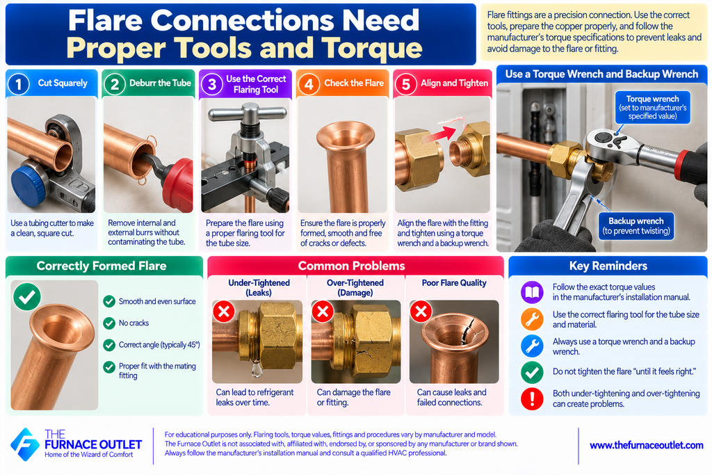
Many conventional mini splits use flare fittings to connect field-installed refrigerant piping to the equipment. This is a precision connection rather than an ordinary plumbing fitting.
The copper should be cut squarely, deburred carefully without contaminating the tubing, and prepared using the correct flaring tool. The flare needs to be properly formed and aligned before tightening.
Manufacturer-specified torque matters because both extremes can create problems. Insufficient tightening can contribute to leakage, while excessive tightening can damage the flare or fitting.
I would use the torque values in the exact installation manual and the appropriate torque and backup wrenches rather than tightening the fitting until it merely “feels right.”
After the refrigerant piping has been assembled, the job is not finished. Conventional field-installed systems generally require leak testing and evacuation according to the manufacturer’s procedures before commissioning.
Pressure testing helps verify the integrity of the field-made refrigerant circuit. Evacuation removes air and moisture before the refrigerant circuit is placed into normal operation.
The required procedures, pressures, vacuum targets, hold times, and refrigerant-handling steps should come from the equipment manufacturer and current industry requirements rather than a generic internet checklist.
This stage is particularly important because an installation can look perfect from outside while still contain a leaking flare, moisture, or non-condensable gases inside the refrigeration circuit.
A mini split commonly leaves the factory with a refrigerant charge intended to accommodate a specified amount of piping. If the actual line set exceeds that allowance, additional refrigerant may be required.
The manufacturer may specify an additional charge in ounces per foot or grams per meter beyond a stated threshold. That figure is model-specific and should not be copied from another 24K system.
If additional refrigerant is required, it should be measured according to the manufacturer’s procedure rather than estimated.
In the United States, EPA Section 608 requirements also apply to covered refrigerant work. EPA states that technicians performing activities reasonably expected to violate the integrity of a stationary appliance’s refrigerant circuit must meet applicable certification requirements. EPA Section 608 Technician Certification Requirements
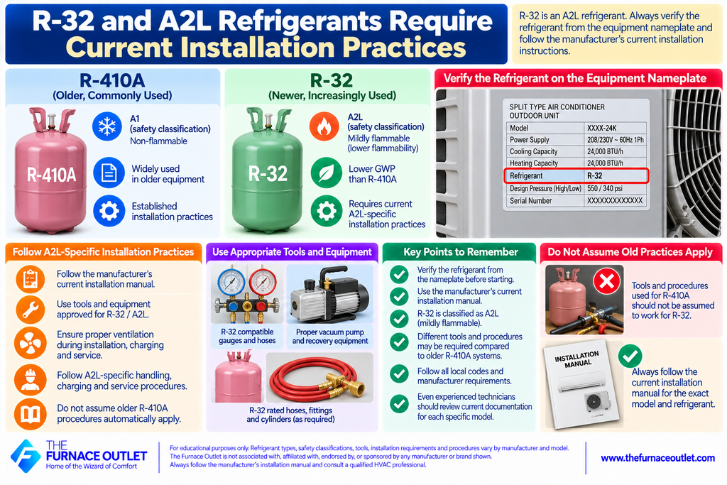
Newer mini splits increasingly use refrigerants such as R-32, which has an A2L safety classification. Older equipment commonly used R-410A, so installers should not automatically assume that every tool and procedure used for an older system transfers unchanged to newer equipment.
I would verify the refrigerant from the equipment nameplate before installation begins and then follow the manufacturer’s instructions regarding tools, charging, ventilation, service procedures, and other A2L-specific requirements.
This is another reason current documentation matters. A technician may have installed hundreds of mini splits successfully, but a new refrigerant, product generation, or equipment design can introduce requirements that did not apply to earlier systems.
Mini-split installation requirements can vary by jurisdiction. Depending on location and scope, electrical, mechanical, building, or other permits and inspections may apply.
I would determine those requirements before work begins rather than after the equipment has been mounted. Local rules can affect disconnects, wiring methods, condenser placement, structural mounting, penetrations, refrigerant work, and other installation details.
Manufacturer instructions establish the equipment requirements, while applicable codes and local authorities establish additional installation obligations. Both need to be considered.

Once the equipment is installed, I want it commissioned, not merely switched on.
Commissioning should include checks appropriate to the particular system and manufacturer’s procedure. That can involve verifying supply voltage, wiring and communication, refrigerant connections, condensate drainage, operating modes, indoor and outdoor fan operation, controls, error codes, temperature response, and other prescribed checks.
The installer should also confirm that filters are accessible, panels are properly secured, insulation and exterior penetrations are finished, and the homeowner understands basic operation and maintenance.
I would retain the model numbers, serial numbers, installation manual, warranty documentation, commissioning information, and any required product-registration confirmation. Those records can become extremely useful years later when parts or service are needed.
Before installation day, I would want the load calculation and zoning decision settled, the exact indoor and outdoor model numbers selected, and the indoor and outdoor mounting positions identified. I would also verify the electrical voltage, MCA, MOCP, dedicated-circuit requirements, disconnect arrangement, line-set diameters, piping-length limits, elevation limits, factory-charge allowance, refrigerant type, condensate route, clearances, and service access.
I would then map the refrigerant, electrical, and drain routes before drilling penetrations. Finally, I would confirm what portions of the installation require qualified or licensed professionals, what permits or inspections apply locally, and exactly how the manufacturer requires the system to be pressure tested, evacuated, charged where necessary, and commissioned.
That preparation can prevent expensive changes once equipment is already attached to the building.

A successful 24,000 BTU mini-split installation starts long before the first mounting screw goes into the wall. Load calculation comes first, zoning and airflow come second, exact equipment selection comes third, and installation planning follows from those decisions.
Once the exact system has been selected, its manual should drive the details. Electrical requirements should come from the nameplate and published MCA/MOCP information. Refrigerant pipe diameters, length limits, elevation restrictions, additional-charge requirements, flare torque, evacuation procedures, clearances, and commissioning instructions should likewise come from the documentation for that equipment.
I would resist shortcuts such as assuming every 24K system needs the same breaker, the same wire, the same copper tubing, the same refrigerant charge, or the same installation procedure. Two products carrying the same nominal 24,000 BTU capacity can be very different machines.
The goal is not simply to get the mini split running on installation day. The goal is to create a system that delivers the required capacity where the building needs it, drains correctly, operates safely, can be serviced properly, and performs as close as possible to the way its manufacturer designed it to perform.
Yes. Since one ton of nominal HVAC capacity equals approximately 12,000 BTU/h, a 24,000 BTU system is commonly described as a 2-ton mini split. That nominal rating does not mean the equipment always produces exactly 24,000 BTU/h, particularly with inverter systems that vary output according to demand.
It depends on the load and floor plan. Even if a home’s calculated load were close to 24,000 BTU/h, one wall-mounted indoor unit may not distribute air effectively to multiple enclosed bedrooms and other separated rooms. Capacity and air distribution should be evaluated separately.
Many U.S.-market 24K systems use 208/230V single-phase power, but the exact electrical requirements must be verified from the model’s nameplate and installation documentation.
There is no universal breaker size based solely on 24,000 BTU capacity. Check the exact equipment’s MCA and maximum overcurrent-protection specifications and have the circuit designed according to manufacturer requirements and applicable electrical code.
Line-set diameter varies by manufacturer and model. Do not purchase refrigerant piping based solely on the system’s BTU rating. Verify the required liquid and gas/suction pipe diameters for the exact indoor and outdoor combination.
The answer depends on the equipment, work involved, and applicable regulations. Mounting and other tasks are different from permanent high-voltage electrical work and work that opens or otherwise affects the refrigerant circuit. EPA Section 608 requirements apply to covered refrigerant activities in the United States, while electrical, mechanical, permitting, and licensing requirements can also apply locally.
Conventional systems with field-installed refrigerant piping generally require evacuation according to the manufacturer’s installation procedure before commissioning. Purpose-designed pre-charged or quick-connect systems can use different procedures, so the exact equipment manual should govern rather than assuming every mini split is commissioned identically.
Editorial & Safety Disclosure: The Furnace Outlet is not associated with, affiliated with, endorsed by, or sponsored by any manufacturer or brand mentioned and does not receive manufacturer compensation for inclusion. This guide is for educational purposes only. HVAC sizing, electrical work, refrigerant piping, charging, A2L requirements, permitting, and installation procedures vary by equipment and jurisdiction. Always follow the current manufacturer’s instructions, applicable codes and regulations, and use appropriately qualified professionals for work that requires them.
https://thefurnaceoutlet.com/best-24000-btu-mini-splits-of-2026-top-2-tonne-systems-compared/