If you want a PTAC that performs like it should, lasts like it should, and doesn’t trip breakers or burn extra power, you have to do the electrical and load planning before you ever pick the model. Most folks skip this part. They measure a wall, eyeball the BTUs, and buy whatever looks right online.
Then they plug it into a circuit that’s already maxed out… or they run the heat strip and discover their panel can’t handle it… or the sleeve ends up half an inch off and airflow gets choked.
A PTAC isn’t just a box that blows hot and cold.
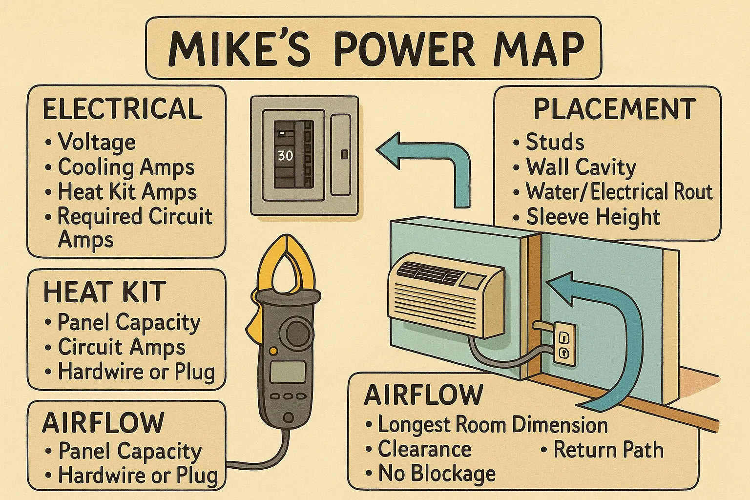
It’s a system, and Mike’s Power Map makes that system work.
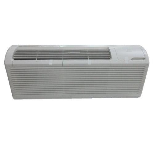
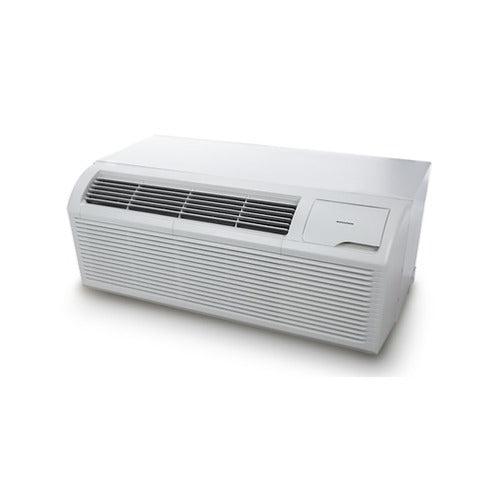
This guide shows you exactly how I calculate electrical load, amperage, placement, breaker sizing, and layout mapping before choosing a PTAC — like the Amana Distinctions 12,000 BTU PTAC with 3.5 kW heat kit
⚡ 1. Why “Power Mapping” Matters More Than BTUs
Most homeowners shop PTACs based on:
-
BTU rating
-
Heat kit size
-
Voltage (115V or 230/208V)
-
Brand name
But the real system design starts with power mapping — figuring out how the unit interacts with:
-
Your home’s electrical panel
-
Circuit load
-
Building wiring
-
Breaker availability
-
Outlet location
-
Heat strip amperage
-
Line placement and airflow
I’ve seen perfect BTU matches fail miserably because the electrical side was ignored.
Here’s what power mapping prevents:
✔️ Breaker tripping
✔️ Overheating wiring
✔️ Loud humming from overloaded circuits
✔️ Voltage drop leading to poor heating
✔️ Dead zones from airflow-blocked wall placements
✔️ Wall sleeves installed in the wrong cavity
A PTAC is only as smart as the system it plugs into.
🔋 2. Step One — Calculate Real Electrical Load (Not What the Box Says)
Before choosing any PTAC, you need to know how much power your room can realistically support.
Know these four numbers:
1. Voltage (115V vs 230/208V)
Most cooling-only or low-watt PTACs come in 115V.
Heat-strip PTACs (3kW+) almost always require 230/208V.
2. PTAC cooling amperage
Usually 6–8 amps for a 12,000 BTU unit.
3. Heat kit amperage
This is the big one.
A 3.5 kW electric heat kit draws roughly 16–17 amps on a 230V circuit.
Source: Power formula (P=VI) + manufacturer specs.
4. Total recommended circuit amperage
Add cooling + heating + startup surge.
For a 12,000 BTU PTAC with 3.5 kW heat strip:
-
Cooling: ~7 amps
-
Heating: ~16 amps
-
Surge: 2–4 amps
Total: ~25–27 amps
You need a 30A dedicated circuit.
This isn’t guesswork — it’s NEC-backed electrical load calculation.
Reference: National Electrical Code (NEC)
🔌 3. Step Two — Check If the Panel Can Actually Handle It
Most homes have 100–200 amp service.
The trick is ensuring you have dedicated capacity for a PTAC.
Mike’s panel check:
-
Locate your main breaker (100A, 125A, 150A, or 200A).
-
Open the panel and check for open breaker slots.
-
Identify existing circuit capacity.
-
Avoid sharing circuits with:
-
Microwaves
-
Space heaters
-
Window ACs
-
Vacuums
-
Kitchen outlets
-
Washer/dryer
-
A PTAC heat strip WILL trip a shared circuit.
If your panel is nearly full:
You may need a subpanel — about $200–$400 for materials.
If your panel is overloaded:
You’d be shocked (pun intended) how many homes are already on the edge.
🧮 4. Step Three — The BTU-to-Room Load Calculation (Mike’s Real-World Formula)
Forget internet “per square foot” charts.
They ignore real heat gain, sun exposure, and airflow geometry.
Mike’s PTAC Sizing Formula:
Start with 20 BTU per square foot (DOE standard)
Source: U.S. Department of Energy — https://www.energy.gov/energysaver/room-air-conditioners
Then adjust:
Add 10–20% BTUs if:
-
Room faces south/west
-
Ceiling > 8 feet
-
Poor insulation
-
Large windows
Add 4,000 BTUs if:
-
It’s an attic room
-
It’s a sunroom
-
It’s a room above a garage
Subtract 10–15% if:
-
Room is shaded
-
Dual-pane windows
-
Adjacent rooms are conditioned
By the time you finish this step, you’ll know the actual BTU requirement — which impacts electrical sizing.
📏 5. Step Four — Map the Wall Cavity, Stud Layout, and Sleeve Placement
PTACs can’t just go “anywhere on the wall.”
Correct placement affects:
-
Airflow
-
Heat balance
-
Noise
-
Electrical routing
-
Line placement
-
Condensate drainage
-
Sleeve structural support
Here’s the exact process:
🔹 1. Find the stud bay
Use a stud finder — ideal width is 16” on center.
🔹 2. Mark the sleeve opening
Most PTAC sleeves require 42” width & ~16” height.
🔹 3. Check wall insulation
Fiberglass insulation often must be trimmed or replaced with rigid foam around the sleeve.
🔹 4. Check for:
-
Water lines
-
Electrical lines
-
Low-voltage wires
-
HVAC ducts
Everything needs rerouting before cutting.
🔹 5. Determine where electrical wiring enters the cavity
The PTAC power cord must reach the outlet without bending or crushing.
🧱 6. Step Five — Determine the Electrical Path (Mike’s Clean Routing Method)
A PTAC needs a short, safe, direct path from panel to outlet.
Mike’s routing rules:
✔️ Use 12/2 for 20A circuits
✔️ Use 10/2 for 30A circuits
✔️ Keep runs under 75 feet to avoid voltage drop
✔️ Use smooth sweeps — no tight bends
✔️ Avoid running parallel to plumbing
✔️ Don’t pierce fire blocks without sealing them
Use a voltage drop calculator to confirm run length:
https://www.calculator.net/voltage-drop-calculator.html
🧯 7. Step Six — Identify Power Accessory Needs
Depending on the PTAC model, you may need:
1. Subbase heater
Keeps condensation from freezing at the floor.
2. Disconnect box
Required in some jurisdictions.
3. Wall sleeve
(E.g., Amana standard PTAC sleeve.)
4. Seal kit
Stops air leakage around the sleeve.
5. Dedicated outlet
Some PTACs hardwire; others plug into a PTAC-rated receptacle.
🧊 8. Step Seven — Map the Line Placement & Airflow Geometry
Now that power checks out, we map airflow.
PTACs move air horizontally, not vertically like mini splits.
That means placement must avoid obstructions like:
-
Beds
-
Sofas
-
Desks
-
Dressers
-
Room dividers
Mike’s airflow rules:
Rule 1: Shoot air toward the longest path of the room.
This gives air enough “runway” to circulate fully.
Rule 2: Maintain 3–5 feet of open space in front.
Rule 3: Don’t place PTAC behind furniture, curtains, or décor.
You’d be surprised how many PTACs suffocate behind drapery.
Rule 4: Ensure cross-flow.
Air needs a place to escape — usually a doorway or hall.
Rule 5: Use the Tri-Zone Flow Method
(From our previous guide.)
Air should reach:
-
The far corner
-
The room center
-
An exit pathway
🔥 9. Step Eight — Choose the Heat Kit (Only After Electrical Mapping)
PTAC heat kits come in:
-
No heat
-
2 kW
-
3 kW
-
3.5 kW
-
5 kW (commercial only)
Here’s the rule:
✔️ If your electrical panel can’t handle 30A, don’t choose a 3+ kW heat kit.
Choose a lower kit OR skip the heat strip entirely.
✔️ If the room needs supplemental winter heat:
A 3.5 kW kit is ideal — like in the Amana Distinctions model.
✔️ If you want maximum efficiency:
Consider adding a heat pump PTAC instead of a large heat strip.
📊 10. Step Nine — Final Circuit, Load & Placement Confirmation
Before purchasing the unit, confirm:
✔️ Room BTU requirement
✔️ Required circuit amperage
✔️ Breaker capacity available
✔️ Wire gauge requirement
✔️ Sleeve placement location
✔️ Airflow geometry compatibility
✔️ Outlet / hardwire method
✔️ Voltage match (115V or 230V)
✔️ Heat kit amperage
✔️ Panel load calculation
Once these checks are done…
Now you’re ready to select the PTAC.
🏆 11. Mike’s Power Map — The Final Checklist (Print This)
Electrical:
-
☐ Panel has open slot
-
☐ Panel load supports new breaker
-
☐ Correct breaker size selected
-
☐ Proper wire gauge chosen
-
☐ Dedicated circuit confirmed
-
☐ Voltage drop acceptable
-
☐ No shared loads
Placement:
-
☐ Studs mapped
-
☐ Wall cavity clear
-
☐ No water/electrical conflicts
-
☐ Sleeve centered
-
☐ Correct height chosen
-
☐ Clear airflow path
Airflow:
-
☐ Air shoots down longest room dimension
-
☐ 3–5 ft clearance
-
☐ No curtains/furniture blockage
-
☐ Return path/open doorway available
-
☐ No dead corners
Heat Kit:
-
☐ 2kW/3kW/3.5kW matched to panel
-
☐ Circuit amperage verified
-
☐ Hardwire or plug type confirmed
🎯 Conclusion: Power Mapping Makes or Breaks a PTAC Installation
Most PTAC problems don’t come from the PTAC itself.
They come from choosing the wrong unit because the home wasn’t power-mapped.
By following Mike’s Power Map:
-
Your breakers stay quiet
-
Your wires stay cool
-
Your room heats evenly
-
Your airflow is optimized
-
Your PTAC lasts longer
-
And your cooling bill stays low
Buy this on Amazon at: https://amzn.to/3WuhnM7
In the next topic we will know more about: Tool-Driven System Design: Mike’s Guide to Choosing the Right Gear Before You Build Anything