Mike Sanders has a simple philosophy about HVAC comfort—one he repeats on every job:
“The unit doesn’t control the room.
The room controls the unit.”
Most installation failures happen not because the equipment is too small, too weak, or poor quality, but because the room’s footprint wasn’t analyzed before the install. That means the unit ends up fighting:
-
the room’s geometry
-
the furniture layout
-
the airflow resistance
-
the thermal load patterns
-
the pressure balance
-
the occupant pathways
…instead of working with them.
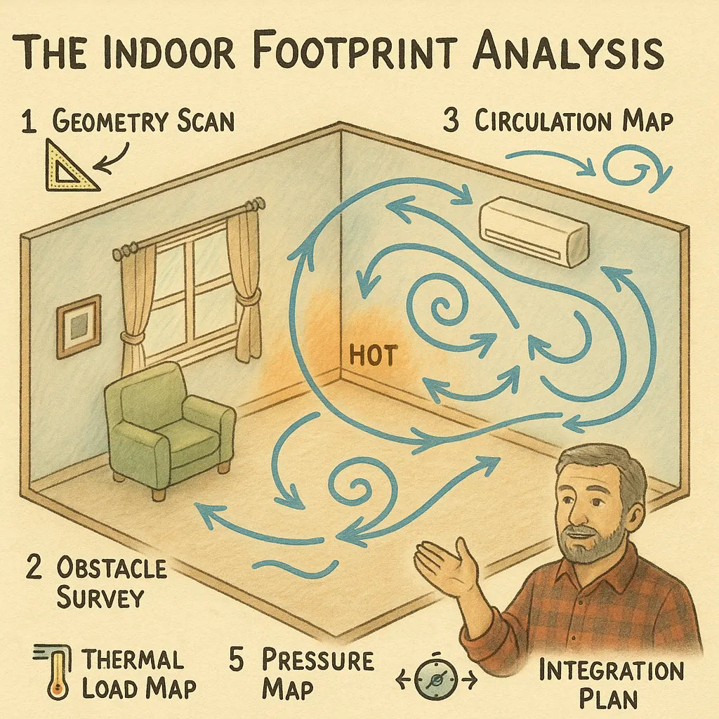
Mike’s Indoor Footprint Analysis is a 6-step room-science framework that ensures the unit operates in harmony with the space. By mapping geometry, objects, circulation pathways, vertical layering, and occupant usage patterns, Mike designs airflow strategies that cut energy waste, eliminate dead zones, and stabilize comfort.
This article breaks down his full process—from diagnostics to airflow modeling—so your wall unit, PTAC, ductless, or central register system never fights the room again.
🧭 1. Mike’s Core Principle: “The Room Has a Shape. Air Fills That Shape.”
The Indoor Footprint Analysis begins with the recognition that comfort is dictated not by equipment BTU size alone but by:
-
room geometry
-
airflow paths
-
obstacles
-
thermal loads
-
human movement patterns
Mike explains it perfectly:
“You can’t put modern equipment into a room built with bad airflow geometry and expect comfort.
You need the room to accept the air first.”
This is why his analysis always comes before installation.
📏 Step 1 — The Geometry Scan: Mapping the 3D Shape of the Room
📐 Icon: Drafting Triangle
Mike begins by analyzing the true room shape—not just the square footage.
He takes measurements of:
-
total width
-
depth
-
ceiling height
-
soffits
-
alcoves
-
bay windows
-
stair connectors
-
angled ceilings
-
knee walls (in attics)
-
offset corners
This forms the Geometry Map, which predicts airflow behavior.
Why it matters
Rooms are not uniform boxes. Even a simple 12×14 room may have:
-
a closet bump-out
-
an offset door
-
a soffit drop
-
a window alcove
Each irregularity changes airflow and affects:
-
throw distance
-
circulation loops
-
return pathways
-
heat-load balance
Cold spots predicted by geometry
Mike identifies likely cold pockets simply by studying the shape:
-
inward corners
-
alcoves
-
edges behind furniture
-
window corners
-
spaces past a partial wall
These become checkpoints for airflow engineering later.
🛋️ Step 2 — The Obstacle Survey: Identifying Resistance Zones
🪑 Icon: Chair + Arrow
Air behaves like water—it flows around objects.
Mike walks the room noting objects that create airflow resistance or “dams”:
-
sofas
-
entertainment centers
-
desks
-
bed frames
-
bookcases
-
tables
-
storage bins
-
large plants
He identifies:
-
vertical resistors (tall furniture)
-
horizontal resistors (beds, tables)
-
edge blockers (couches against walls)
-
corner containers (L-shaped sectional seats)
Mike’s rule: “Every object creates a shadow.”
Behind every object is an airflow shadow zone where:
-
cold air pools
-
humidity builds
-
return flow collapses
These shadows multiply when furniture touches walls or corners.
🔄 Step 3 — The Circulation Map: Tracking Natural Airflow Loops
🌬️ Icon: Circular Arrow
Once he knows the obstacles, Mike studies the circulating air pathways the room already supports.
Air wants to travel in loops, not straight lines.
Mike identifies:
-
primary loop (largest circulation path)
-
secondary loop (between furniture zones)
-
micro-loops (corner convection pockets)
He also identifies loop killers:
-
closed doors
-
narrow hall transitions
-
furniture pressed against walls
-
blocked return edges
Why circulation matters
Even if a unit delivers the right BTUs:
-
if circulation collapses
-
comfort collapses
Rooms must allow air to:
-
move forward
-
diffuse
-
drop
-
return
-
repeat
This is the foundation of both cooling and heating performance.
🌡️ Step 4 — The Thermal Load Map: Finding Where the Heat Lives
🔥 Icon: Thermometer
Mike uses a mix of:
-
IR thermometer
-
humidity sensor
-
window orientation
-
shading
-
appliance load
He maps the “thermal footprint” which includes:
-
window heat gains
-
exterior wall chill
-
radiant heating patterns
-
people heat load
-
electronics heat loads
Thermal load points cause:
-
hot zones
-
cold zones
-
humidity imbalance
-
pressure differences
Mike overlays these heat signatures onto the geometry map from Step 1.
This shows him where the unit must aim its airflow and which areas need support.
Reference:
ASHRAE Load Basics – https://www.ashrae.org/technical-resources
🪟 Step 5 — The Pressure Map: Ensuring the Room Can Breathe
🌀 Icon: Pressure Gauge
Pressure determines where air moves.
Mike checks:
-
door undercut
-
hallway connections
-
window leakage
-
wall leakage
-
return path openness
-
micro-return viability
Signs the unit is “fighting the room”
-
door slams shut when AC turns on
-
stagnant corners
-
floor-level cold zones
-
humidity trapped in corners
-
warm layer near ceiling
-
inconsistent thermostat readings
These mean pressure imbalance—the air is trapped and cannot circulate.
Mike regulates this by:
-
opening return pathways
-
creating micro-return loops
-
adjusting airflow direction
-
opening doors/staggering airflow
Reference:
DOE Home Ventilation Concepts – https://energy.gov/energysaver/whole-house-ventilation
🧩 Step 6 — The Integration Plan: Aligning Airflow With Room Behavior
🧭 Icon: Compass + Arrows
Once the room’s geometry, obstacles, circulation, heat loads, and pressure patterns are known, Mike executes alignment.
This ensures the unit and room work together.
Mike sets:
📌 1. Supply Direction
He aims airflow at:
-
the longest pathway
-
the biggest heat-load area
-
or the most restrictive zone requiring break-through
This ensures full-room reach.
📌 2. Vertical Vane Angle
He uses:
-
downward airflow for heating
-
upward airflow for cooling
-
slight lateral tilt to break dead corners
This balances vertical stratification.
📌 3. Fan Speed Logic
Mike rarely uses AUTO.
He sets:
-
Medium for heating
-
Medium/High for cooling
-
Low at night for gentle circulation
Fan speed dramatically affects circulation stability.
📌 4. Micro-Fan Support (If Needed)
He adds:
-
floor-return boosters
-
corner extraction fans
-
cross-flow circulators
These ensure return-loop stability in difficult rooms.
📌 5. Furniture Corrections
Instead of rearranging whole rooms, Mike uses micro-adjustments:
-
pull sofa forward 2 inches
-
rotate a chair 10 degrees
-
lift end tables slightly
-
space bed from wall
These tiny changes create huge airflow improvements.
📌 6. Thermal Corrections
He reduces thermal conflict by:
-
redirecting airflow toward windows
-
insulating cold walls
-
using thermal curtains
-
adding blinds or reflective film
Reference:
Window efficiency & treatments – https://energy.gov/energysaver/energy-efficient-window-attachments
📈 What the Indoor Footprint Analysis Achieves
Homeowners experience immediate improvements:
✔ Balanced temperature across the entire room
No more cold corners or hot pockets.
✔ Real-world comfort matches thermostat reading
The room feels as warm/cool as the display says.
✔ Faster heating & cooling times
Circulation becomes efficient and predictable.
✔ Less energy wasted
Unit runs smoother, with longer cycles and fewer spikes.
✔ Reduced noise
No turbulence from blocked airflow.
✔ Better humidity balance
Return pathways stabilize moisture distribution.
✔ Optimal performance from ANY unit
Even budget through-the-wall systems feel premium.
🧠 Why Mike’s Method Works Better Than Manufacturer Guidelines
Manufacturers give:
-
clearance numbers
-
minimum distances
-
installation height
They cannot account for:
-
your sofa
-
your alcove geometry
-
your split-level transition
-
your window heat-load
-
the way you use the room
Mike’s Indoor Footprint Analysis is the missing half of proper installation.
🔧 Bonus: Mike’s Red Flags That Tell Him a Unit Is “Fighting the Room”
He looks for:
⚠️ Hot ceiling / cold floor
Stratification from trapped airflow.
⚠️ Warm air blowing but room still cold
Return flow failure.
⚠️ Cold pockets in corners
Geometry-induced dead zones.
⚠️ Door pulls shut by pressure
Imbalanced circulation.
⚠️ Humidity lingering in one zone
Weak return pathway.
⚠️ Airflow “stalls” halfway across room
Furniture or geometry blocking forward motion.
Each of these is solvable through footprint correction.
🔗 External Verified Sources
-
NIST – Sound and Vibration Control Principles
https://www.nist.gov -
Energy Department – Air Sealing Techniques
https://energy.gov/energysaver/weatherize/air-sealing-your-home -
EPA Indoor Noise & Acoustics Overview
https://www.epa.gov/indoor-air-quality-iaq -
Rockwool Acoustic Performance Data
https://www.rockwool.com -
ASHRAE Fundamentals: HVAC Noise Control
https://www.ashrae.org/technical-resources -
Acoustic Insulation Standards (BCA/ISO)
https://www.iso.org
Buy this on Amazon at: https://amzn.to/47M5ozS
In the next topic we will know more about: The Load Map Blueprint: How Mike Designs a Room Around the Unit—Not the Other Way Around

