Most homeowners shop for a through-the-wall AC/heat combo based on square footage.
Mike Sanders doesn’t.
He starts with something far more reliable: the room’s load map.
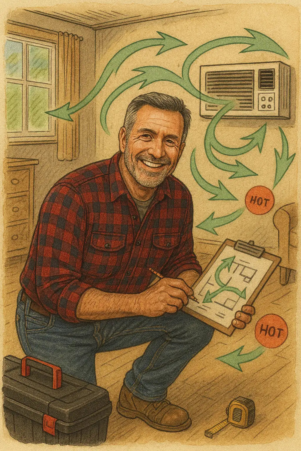
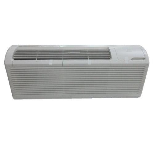
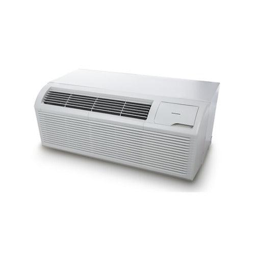
To Mike, every room is a micro-climate—a unique combination of geometry, materials, obstacles, heat sources, and occupant habits. The Amana 11,900 BTU Through-the-Wall AC with Electric Heat (Model PBE123J35AA) is powerful, but its performance depends entirely on whether the space is designed for it.
This blueprint walks through Mike’s room-first approach—how he measures, analyzes, maps, and orchestrates a room so the equipment performs at peak efficiency with whisper-quiet comfort.
📐 1. Mike’s First Principle: “The Room Is the System.”
Mike always says:
“Installing a wall unit isn’t a product decision. It’s a system design decision.”
The unit isn’t the system. The room is the system.
Your job is to make sure the unit, the room, and the thermal behavior of the home are aligned.
Why this principle matters
Most people:
-
pick a BTU size
-
find a convenient spot on the outside wall
-
cut the hole
-
mount the sleeve
-
hope for the best
Mike does the opposite:
-
Study the room.
-
Identify its heat loads.
-
Map the air pathways.
-
Determine airflow obstacles.
-
THEN choose the location and orientation of the unit.
And that difference is why his installs feel more even, more efficient, and more comfortable—especially in tricky rooms.
🧭 2. Step One: Mike’s Full-Room Thermal Load Scan
Before he even touches a tape measure, Mike performs a thermal load scan, which includes both obvious and “hidden” load factors.
🔆 2.1. Solar Exposure Map
You can't design airflow until you know where the heat is coming from.
Mike evaluates:
-
Cardinal window direction
-
Window size & number
-
Shading
-
Wall insulation value
-
Roof overhang
-
Glass type (single vs double vs low-E)
A west-facing room can feel 10°F hotter than a shaded north-facing room, even if they’re identical sizes.
Reference:
Solar heat gain factors (ASHRAE) – https://www.ashrae.org/technical-resources
🔥 2.2. Internal Heat Sources
Mike lists every heat-producing element:
-
TV and electronics
-
Gaming consoles
-
Lamps
-
Desktop PCs
-
Fridges or mini-fridges
-
Aquarium lights
-
Workout equipment
-
People (yes—humans are heat sources)
Even a modern TV can add 100–150 BTUs of load.
💨 2.3. Airflow Restrictions and Choke Points
This is where most DIY installs fail.
Mike checks:
-
Big furniture blocking paths
-
Sectionals near the wall
-
Open vs closed floor plan transitions
-
Narrow hallways that kill return airflow
-
Door swing directions
-
Ventilation paths (or lack thereof)
If the airflow can’t circulate, the unit becomes a local air chiller—not a room conditioner.
🌡️ 2.4. Insulation and Envelope Weak Points
He physically tests:
-
Wall temperature using an IR thermometer
-
Window drafts
-
Floor-to-ceiling temp stratification
-
Door gaps
-
Ceiling insulation
Hot or cold walls show up instantly on his thermal readings.
Reference:
Thermal imaging explanation – https://energy.gov/energysaver/home-energy-audits
📏 3. Step Two: Mike’s Room Geometry & Layout Mapping
Thermal mapping identifies where the heat comes from.
Geometry mapping identifies where the air must go.
This is where Mike acts like a structural engineer.
📎 3.1. The Volume, Not Square Footage Rule
BTUs are rated by cubic feet, not square feet.
Mike measures:
-
full width
-
full depth
-
true ceiling height
-
soffits
-
vaulted zones
-
beam drops
-
stair openings
A 12x12 room at 8 ft high is 1,152 cubic feet.
But with a lofted ceiling at 11 ft, it’s 1,584 cubic feet—a 37% increase.
🪑 3.2. The Furniture Heat-Shadow Effect
Mike traces “shadow zones” behind furniture where air circulation dies.
Common culprits:
-
Tall bookshelves
-
Headboards
-
Sofas against walls
-
TV stands
-
Corner desks
Where air can’t reach, temperature drift is guaranteed.
🔁 3.3. Circulation Path Mapping
Air needs a path and a return route.
Mike uses airflow chalking (a thin fog test or simple tissue test):
-
identifies stagnant pockets
-
sees how air wraps around corners
-
evaluates if the door position allows loop circulation
If the room can’t cycle air back to the unit, it becomes temperature-layered.
📍 4. Step Three: Mike’s Optimal Unit Placement Algorithm
Now that the room is fully mapped, Mike chooses the placement using a strict rule set.
He doesn’t use “center of wall.”
He uses center of airflow opportunity.
Below are the factors that guide his decision.
🎯 4.1. The 12–15 Foot Throw Zone Rule
The PBE123J35AA has an optimal cooling throw of around 12–15 feet.
Mike places the unit so its throw:
-
reaches the farthest point of the room
-
avoids hitting one object too quickly
-
spreads across the longest open plane of air
This ensures:
-
low noise
-
maximum air mixing
-
uniform temperature
⬅️ 4.2. The Asymmetry Advantage
Mike rarely installs a unit dead-center.
Why?
Because center placement:
-
creates symmetry, but
-
also creates mirror-image cold pockets
Instead, Mike positions units:
-
25–35% from one side of the wall
-
angled toward the highest load zone
-
with a cross-flow path
This is a “flow bias” strategy that stabilizes the hottest area first.
↩️ 4.3. The Return Loop Requirement
Mike ensures there is at least:
-
3–4 ft of clearance in front
-
a clear return path looping the room
-
no dead-end corners
-
no door traps
If the room is oddly shaped, he will:
-
add a micro-fan
-
change furniture layout
-
or slightly offset the unit placement
But he never compromises the return path.
⚡ 4.4. Heat Mode Geometry
For electric heat operation:
Warm air rises, so Mike changes:
-
output direction
-
vane angle
-
circulation path
-
interior fan support
He often points the warm air along a long wall instead of straight out.
This prevents:
-
heat stratification
-
cold-floor syndrome
-
corner overheating
Warm air behaves differently than cold air—Mike models for both.
🧊 5. Step Four: Predicting Cooling Performance Using Load Points
Once the placement is set, Mike predicts the real-world performance using load points.
Load points determine:
-
how hard the unit will work
-
what the hottest and coldest zones will be
-
where micro-adjustments are needed
He uses the following tools:
-
IR thermometer
-
Laser tape
-
Airflow meter
-
Psychrometer
-
CADR helpers
Common load points:
-
sun-heavy windows
-
walls adjacent to garages or attics
-
interior corner zones
-
low-return “dead legs”
-
zones with heat-generating devices
This analysis lets Mike forecast how the unit will behave before it's installed.
📊 6. Step Five: Designing the Air Path (Mike’s Airflow Geometry)
Mike now models the air path using three components:
-
Primary throw path
-
Cross-flow path
-
Return loop
This ensures:
-
no cold corners
-
no stagnant heat pockets
-
equalized sensation temperature
He calls this the Three-Path Law.
🌀 6.1. Primary Throw Path
This is the main cooling/heating direction.
Mike ensures:
-
no immediate obstacles
-
the path reaches the farthest zones
-
the air diffuses naturally along surfaces
Smooth, uninterrupted airflow = efficient cooling.
🔄 6.2. Cross-Flow Path
The secondary spread helps balance the room.
Mike adjusts:
-
vane angle
-
fan direction
-
circulation fans if needed
Cross-flow reduces load difference between left and right halves of the room.
🔁 6.3. Return Loop
The air must find its way back.
Mike evaluates:
-
door position
-
furniture
-
wall angles
-
soft partitions
-
curtains, tall items, and dividers
Without a return path, the room never stabilizes.
🛠️ 7. Step Six: Building the Room Around the Unit
Once everything is modeled, Mike makes physical layout changes.
He may:
-
reposition furniture
-
open a pathway
-
add micro-fans
-
extend return routing
-
close strategic vents
-
block solar load areas
He also evaluates:
📚 7.1. Furniture Placement Corrections
He clears:
-
2 ft to each side
-
3–4 ft front distance
-
airflow paths across room width
🌬️ 7.2. Micro-Circulation Devices
Tiny, quiet fans placed strategically help air wrap around obstacles.
Mike uses them to:
-
remove dead zones
-
push cool air up stairs
-
eliminate warm corners
🌤️ 7.3. Solar Load Mitigation
He may suggest:
-
blackout curtains
-
low-E film
-
window shading
-
thermal drapes
Solar control dramatically reduces stress on the AC.
Reference:
Low-E film performance – https://www.energy.gov/energysaver/energy-efficient-window-attachments
📡 8. Step Seven: Mike’s Sensor-Driven Calibration Method
Now the room is prepped and the unit installed, Mike uses sensors to fine-tune performance.
He monitors:
-
throw velocity
-
room humidity
-
supply temperature drop
-
temperature parity across room
-
pressure equilibrium
Two measurements matter most:
1. ΔT (Temperature Drop)
Ideal drop across the coil: 15–20°F
2. Stratification Delta
Difference between ceiling and floor: less than 4°F
Anything higher means airflow geometry needs tweaking.
📘 9. Step Eight: Mike’s Data-Driven Fan Speed Logic
Most homeowners keep their AC on Auto.
Mike refuses to.
He adjusts fan speed based on the room’s geometry.
🌡️ Cooling
-
Larger rooms: Medium
-
High solar load: High
-
Small symmetrical rooms: Low
-
Odd-shaped rooms: Medium + micro-fan assist
🔥 Heating
To avoid heat-overshoot:
-
Low or Medium only
-
Vane angle lowered
-
Circulation fans reversed
🧱 10. Step Nine: Insulation Corrections and Load Equalization
If the room has “problem walls,” Mike reinforces:
-
wall insulation
-
door seals
-
window gaps
-
floor-cover thermal leaks
Even a 5% reduction in infiltration improves unit performance noticeably.
📏 11. Step Ten: The Final Load Map Score
Mike scores each room based on:
| Category | Weight | Target |
|---|---|---|
| Solar Load | 25% | Low/Moderate |
| Geometry Complexity | 20% | Low |
| Return Path Quality | 25% | High |
| Airflow Obstructions | 15% | Minimal |
| Equip Alignment | 15% | Optimal |
A perfect system isn’t the goal.
A balanced one is.
🔧 12. What Homeowners Get When Mike Designs Around the Unit
Results:
-
Fewer hot/cold spots
-
Lower energy use
-
Faster cooling
-
Faster heating response
-
Better humidity control
-
Quiet operation
-
Longer equipment life
-
Higher comfort consistency
The room works with the unit—not against it.
Buy this on Amazon at: https://amzn.to/47M5ozS
In the next topic we will know more about: Envelope Engineering for Wall Units: Mike’s Method for Stopping Thermal Bleed at the Cutout

