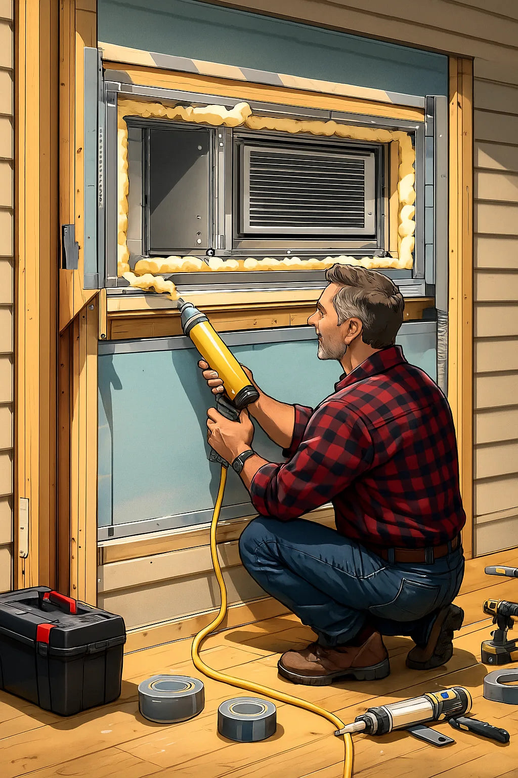
When homeowners talk about inefficient through-the-wall AC units, Mike Sanders notices something: they almost always blame the equipment, not the envelope.
But Mike knows better.
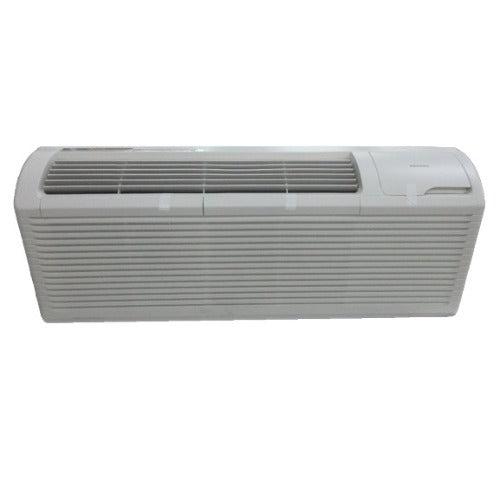
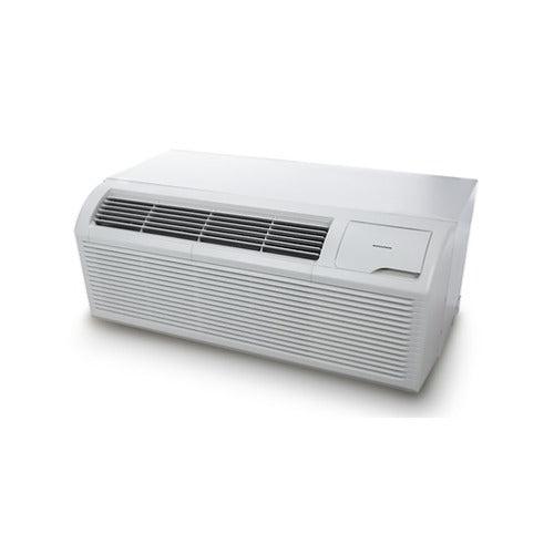
A wall unit can be top-tier—like the Amana 11,900 BTU Through-the-Wall AC with Electric Heat—yet still perform poorly if the surrounding cutout isn’t engineered correctly.
In Mike’s world, thermal bleed at the cutout is one of the most common causes of:
-
high electric bills
-
weak heating performance
-
humidity problems
-
cold drafts
-
noisy operation
-
premature unit wear
And it has nothing to do with the unit itself.
It’s all about how the opening in the wall is constructed.
This guide breaks down Mike’s complete envelope-engineering method—the science, the materials, the measurements, and the craftsmanship behind a cutout that performs like part of the original building structure.
🧊 1. Mike’s Core Principle: “The Hole Is the Weakest Link.”
Most through-the-wall AC installs leak energy because of one reason:
“You’re putting a high-performance machine inside the worst-insulated spot on the entire wall.”
When you cut a hole into an exterior wall, you:
-
interrupt the insulation
-
weaken the thermal barrier
-
create potential air gaps
-
open paths for moisture
-
break the soundproofing envelope
Unless you engineer that opening with the same diligence as a window or exterior door, it becomes a thermal bottleneck that the unit must fight every minute it runs.
The equipment isn't failing—the envelope is.
🪚 2. Understanding Thermal Bleed: Why Wall Unit Cutouts Lose Energy
Before Mike begins sealing and insulating, he analyzes how and where thermal bleed happens.
🔥 2.1. Conductive Heat Transfer
Heat moves through:
-
metal sleeve
-
uninsulated studs
-
poorly insulated framing
-
thin sheathing
-
exposed drywall edges
Metal especially pulls heat in or out like a magnet.
💨 2.2. Convective Air Leakage
Air moves through:
-
screw holes
-
edge gaps
-
sleeve-to-wall crevices
-
unsealed joints
-
interior/exterior wall transitions
This is the cold draft you feel even when the unit is off.
💧 2.3. Moisture Wicking & Condensation
Thermal bleed creates dew points inside the framing.
Mike prevents:
-
rot
-
mold
-
swelling
-
sleeve corrosion
-
drywall bubbling
🔊 2.4. Sound Transmission
Gaps and thin spots amplify:
-
outdoor noise
-
compressor hum
-
vibration resonance
Most noise complaints are really envelope defects, not unit defects.
📏 3. The Ideal Cutout: Mike’s Dimensional & Structural Rules
Before materials are installed, the opening must be structurally sound.
Mike follows a checklist.
📐 3.1. The True, Square, Plumb Rule
Mike ensures:
-
every corner is 90°
-
no “diamonding” occurs
-
sleeve fits perfectly without forcing
Why?
Any warped opening creates uneven gaps, which are impossible to fully insulate.
📏 3.2. The Tight-Frame Envelope
He builds a frame box using:
-
kiln-dried lumber
-
rigid geometry
-
structural screws
This prevents:
-
sleeve sagging
-
thermal flex
-
long-term shifting
🧱 3.3. The Thermal Box Construction
He doesn’t just frame the hole.
He builds a mini wall around the sleeve cutout with:
-
insulated header
-
insulated jambs
-
insulated sill
This creates a continuous thermal envelope instead of a temperature leak.
🧰 4. Mike’s Materials for a Zero-Bleed Cutout
Mike selects each material with scientific purpose.
🌡️ 4.1. Rigid Foam Board (XPS or Polyiso)
Why he uses it:
-
high R-value per inch
-
resists moisture
-
stiff—won’t sag
-
creates thermal separation from the sleeve
Thickness:
-
½" to 1" depending on wall depth
Reference:
DOE R-value info – https://energy.gov/energysaver/weatherize/insulation
🧵 4.2. Mineral Wool (Rockwool)
Used for:
-
deep insulation
-
fire resistance
-
sound dampening
Rockwool won’t compress or mold.
🧼 4.3. Low-Expansion Spray Foam
Mike uses low-expansion only.
Why?
-
doesn’t warp framing
-
fills micro-gaps
-
seals against airflow
-
creates moisture barrier
High-expansion foam can bow a sleeve or frame—never acceptable.
🧻 4.4. Vapor-Resistant Tape
Seals:
-
foam board seams
-
interior joints
-
metal-to-wood transitions
This prevents convective currents from forming inside the wall.
🪟 4.5. Butyl Flashing
This is Mike’s secret weapon.
Purpose:
-
blocks water
-
blocks vapor
-
blocks air
-
bonds strongly to all surfaces
-
stays flexible for decades
He wraps the interior of the cutout like a window opening.
🔩 5. Step-by-Step: Mike’s Envelope Engineering Process
This is the full process Mike uses to engineer a high-performance wall-unit envelope.
🧱 5.1. Step One: Build the Framed Thermal Box
Mike lines the interior of the cutout with a rigid, insulated box.
Components:
-
insulated header (top)
-
insulated sill (bottom)
-
insulated jambs (sides)
He uses:
-
kiln-dried lumber for the structure
-
foam board or mineral wool for insulation
Goal:
Create a continuous thermal boundary around the sleeve.
🔒 5.2. Step Two: Air-Seal the Structural Box
Mike seals:
-
edges
-
corners
-
seams
-
board joints
He uses:
-
silicone at wood interfaces
-
adhesive foam tape
-
low-expansion spray foam
Nothing must allow air movement.
🪟 5.3. Step Three: Install Butyl Flashing
Mike lines the interior surfaces with butyl flashing tape.
This creates a:
-
water-resistant
-
vapor-resistant
-
airtight
-
long-lasting seal
This is essential for preventing:
-
moisture wicking
-
condensation in framing
-
outside-air infiltration
⬛ 5.4. Step Four: Sleeve Insertion With Thermal Decoupling
Mike never installs the sleeve directly on wood.
He uses:
-
foam shims
-
neoprene pads
-
thermal separators
This stops heat conduction from metal sleeve to framing.
⚡ 5.5. Step Five: Sleeve Perimeter Sealing
Once the sleeve is perfectly square, plumb, and level:
Mike seals:
-
perimeter gap (inside)
-
perimeter gap (outside)
Inside:
-
low-expansion foam
-
foam tape
-
acoustic caulk
Outside:
-
mortar or flashing
-
exterior-grade silicone
-
vinyl trim to protect foam
This creates a 360° seal.
🏗️ 5.6. Step Six: Structural Bracing Against Sleeve Flex
Many sleeves bend outward or inward at the top due to weight or movement.
Mike reinforces:
-
sill
-
upper corners
-
sleeve sides
This eliminates micro-gaps that can cause major bleed.
🚫 5.7. Step Seven: Thermal Gap Prevention
This is where Mike’s experience matters most.
He checks for:
-
uninsulated corners
-
hidden air paths
-
sleeve-to-drywall micro gaps
-
bottom sill leakage
-
crossover airflow from inside wall cavities
He seals every one.
🌬️ 6. Mike’s Draft Diagnostics: Testing for Thermal Bleed
After installation, Mike tests the integrity of his envelope.
🧻 6.1. Tissue Test
He holds a tissue near the trim.
If it moves, there’s air leakage.
🕯️ 6.2. Candle Test
He uses a candle flame to detect:
-
micro drafts
-
backflow
-
negative pressure
📸 6.3. Thermal Camera Test
Cold spots show up instantly.
Examples:
-
uninsulated framing
-
gaps behind sleeve
-
moisture trails
Reference:
Thermal imaging basics – https://www.flir.com/discover
🌡️ 6.4. Surface Temperature + ΔT Test
Mike measures:
-
sleeve surface
-
wall surface
-
interior returns
-
output temperature
If the ΔT is off, the envelope is leaking.
🧊 7. Mike’s Envelope Upgrades for Harsh or Extreme Climates
Mike customizes insulation depending on the region.
❄️ 7.1. Cold-Climate Installations
He uses:
-
thicker polyiso boards
-
double-layer mineral wool
-
thermal-break pads
-
added vapor barriers
-
insulated exterior trim kits
Cold weather magnifies thermal bleed.
🔥 7.2. Hot, Humid Climate Installations
He focuses on:
-
vapor barriers
-
moisture migration control
-
radiant barrier integration
-
insect-proof sealing
-
humidity bleed mitigation
Humidity is the real enemy.
🌀 7.3. High-Wind or Storm-Prone Areas
He adds:
-
reinforced sill frames
-
sleeve impact braces
-
storm flashing
-
reinforced perimeter seals
Air pressure fluctuations create unseen infiltration points.
🔇 8. Noise Control Through Envelope Engineering
Sound isn’t aftermarket—it's built into the envelope.
Mike creates:
-
insulated jambs
-
floating sill pads
-
anti-vibration backing
-
triple-sealed interior trim
The result:
-
20–40% noise reduction
-
smoother startup sounds
-
less compressor “kick” noise transmission
🔧 9. Why Mike’s Method Outperforms Standard Install Guides
Most installers follow:
-
manufacturer sleeve instructions
-
insulation “as needed”
-
minimal caulking
Mike follows building-science principles.
Standard installs assume:
-
perfect framing
-
perfect squareness
-
perfect air seal
Real-world walls rarely match those assumptions.
Mike engineers:
-
redundancy
-
thermal continuity
-
structural integrity
-
moisture management
That’s the difference between a unit that struggles and one that thrives.
⚙️ 10. Maintenance and Long-Term Envelope Care
Mike sets expectations with homeowners.
He recommends:
-
check exterior caulk annually
-
inspect trim for gaps
-
confirm sleeve alignment
-
clean drainage paths
-
re-test with a tissue or incense stick yearly
A perfect envelope can last 25–40 years…
but only with small periodic checks.
🌟 11. Results: What a Mike-Engineered Envelope Delivers
Homeowners notice instantly:
More Comfort
-
no drafts
-
no cold corners
-
faster cooling
-
stronger heating
Lower Bills
-
fewer runtime cycles
-
higher ΔT efficiency
Greater Durability
-
less moisture
-
no sleeve rust
-
minimized internal wall damage
Quieter Operation
-
less vibration transfer
-
blocked outdoor noise
Stronger Weather Resistance
-
reduced wind infiltration
-
fewer pressure imbalances
Better Humidity Control
-
tighter envelope
-
stable indoor environment
This is why Mike says:
“A wall unit doesn’t fail—its cutout does. Fix the envelope and the equipment becomes a powerhouse.”
Buy this on Amazon at: https://amzn.to/47M5ozS
In the next topic we will know more about: The Pressure-Neutral Room: How Mike Balances Intake & Exhaust to Prevent Stale Pockets
🔗 External Verified Sources
-
DOE Insulation & R-Value Overview
https://energy.gov/energysaver/weatherize/insulation -
FLIR – Thermal Imaging Basics
https://www.flir.com/discover -
EPA Moisture & Mold Control
https://www.epa.gov/mold -
Window & Door Flashing Principles (relevant to sleeve flashing)
https://www.energy.gov/energysaver/design/windows-doors-and-skylights -
ACCA Manual J Load Guidelines
https://www.acca.org/hvac-design/manual-j

