Most homeowners think ductwork is sized for the air conditioner. Most contractors still design around the cooling tonnage. But Mike Sanders — who has installed more systems than most people will ever see — teaches something very different:
“Air conditioning is easy. Heating is unforgiving. So I size ducts for the furnace — every time.”
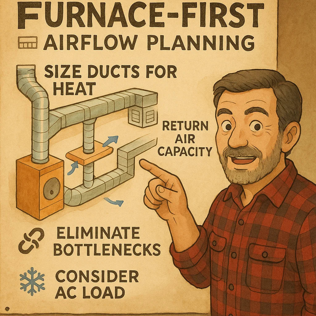
This is the foundation of Mike’s Furnace-First Airflow Planning philosophy. And it’s the reason his systems run quieter, cycle smoother, heat evenly, and avoid the airflow bottlenecks that destroy the efficiency of modern high-static SEER2 equipment.
In this article, you’ll learn why 120,000 BTU furnaces demand a different duct sizing strategy, why AC-based designs fail, and how Mike maps out airflow pathways to handle the demands of high-output heating.
Let’s dive in.
🧠 1. Why Furnace-First Airflow Planning Matters
Mike starts every design with a simple truth:
Heat requires more airflow than cooling — and way more stability.
Here’s what that means.
🔥 1.1 Heating Needs Higher CFM Per BTU Than Cooling Does
Cooling airflow is typically:
❄️ AC Airflow Rule of Thumb
350–450 CFM per ton
= 1400–1800 CFM for a 4-ton system
But heating is harder on airflow.
🔥 120k BTU Heating Airflow Requirement
1200–2000+ CFM, depending on furnace stage and temperature rise.
A 120,000 BTU furnace uses:
-
higher blower RPM
-
higher static pressure
-
faster air expansion across the heat exchanger
-
tighter limits on duct restriction
A duct system built for AC airflow alone often:
-
overheats during furnace operation
-
triggers limit switches
-
short cycles
-
creates hot/cold room imbalance
-
increases utility bills
-
reduces furnace lifespan
This is why Mike says:
“If it can handle the furnace, it can handle anything.”
🎚️ 1.2 The Furnace Has Stricter Safety and Performance Limits
High-output furnaces have:
-
ignition temperature thresholds
-
maximum temperature rise
-
blower RPM limits
-
limit switch triggers
If ducts are undersized, the furnace overheats before the home heats up.
That means:
-
frequent shutdowns
-
uneven room temperatures
-
cracked heat exchangers
-
warranty-voiding operating conditions
External Link: Understanding furnace temperature rise
https://www.energy.gov/energysaver/furnaces-and-boilers
💨 1.3 Heating Air Is More Sensitive to Restriction Than Cooling Air
Cold air is dense. Warm air expands.
Warm expanded air requires:
-
more duct volume
-
larger trunk transitions
-
smoother airflow paths
If ducts are too small:
-
friction increases
-
blower RPM spikes
-
heat exchanger overheats
-
supply air velocity becomes loud
-
return air becomes starved
This is why AC-only duct designs fail the moment winter arrives.
🧱 2. Why Legacy Homes Struggle With 120k BTU Furnaces
Older duct systems were often built for:
-
60k–80k BTU furnaces
-
R-22 air conditioners
-
PSC blower motors
-
1970–2005 airflow rules
This means:
-
6” supply branches everywhere
-
small return plenums
-
tiny filter racks
-
low R-value duct insulation
-
lightweight, low-pressure trunks
A modern 120k BTU furnace with a high-static ECM blower will overpower this duct system instantly.
Symptoms include:
-
Whooshing vents
-
Hot upstairs, cold downstairs
-
Furnace shutting off after a few minutes
-
AC coil icing in summer
-
High energy bills year-round
-
Loud blower operation
Mike’s solution is simple:
“Design around heating airflow. Cooling will fall perfectly into place.”
📐 3. Mike’s Furnace-First Airflow Formula
Mike uses a highly structured formula to ensure the duct system is ready for the 120k BTU furnace at full fire.
📏 3.1 Step 1: Calculate Required CFM for the Furnace
Every furnace has a rated temperature rise, usually:
35°F – 65°F
Using furnace engineering data, Mike determines airflow:
CFM = BTU Output ÷ (1.08 × Temperature Rise)
Example for 120k BTU:
-
At 40°F rise: 2778 CFM
-
At 55°F rise: 2043 CFM
-
At 65°F rise: 1703 CFM
Most 120k units operate best around 1,800–2,200 CFM.
This is MUCH higher than the airflow for a 3.5–4-ton AC system.
🌀 3.2 Step 2: Map Supply Duct Capacities
Mike sizes trunks using:
Minimum Trunk Diameter (120k furnace)
-
18" round
or -
20"x8" rectangular (minimum)
-
24"x8" or larger (preferred for quiet airflow)
Then he sizes branches based on room loads:
-
6" → ~75 CFM
-
7" → ~125 CFM
-
8" → ~200 CFM
Mike’s Rules:
-
No more than 10–12 supply runs of 6"
-
Any run >25 feet must be upsized
-
Second floor MUST get larger ducts than first floor
-
No 90° elbows on the plenum
🫁 3.3 Step 3: Return Air Is Doubled
Mike sizes returns to exceed supply airflow.
Return Rules:
-
At least two returns per 120k furnace
-
No return smaller than 14" round
-
Return filter area of 3–4 sq ft minimum
-
Prefer 2" or 4" pleated filters
-
One return centrally located
-
One return for the second floor
🌬️ 3.4 Step 4: Eliminate Pressure Bottlenecks
Mike checks for:
-
crushed flex duct
-
kinks
-
sagging runs
-
unreinforced elbows
-
undersized boots
-
closed-off rooms
-
restrictive grilles
Most “furnace issues” come from airflow bottlenecks, not the furnace itself.
🧊 3.5 Step 5: Consider Cooling as a Secondary Load
Once the furnace airflow is correct:
-
The AC air volume is automatically sufficient
-
Static pressure matches SEER2 specs
-
Coil heat transfer improves
-
Cooling becomes quieter
This is why Mike uses furnace-first math for duct planning.
📊 4. Furnace vs. AC Load: Two Completely Different Airflow Profiles
Understanding the physics is key.
☀️ 4.1 AC Load Profile
-
Lower airflow
-
Lower discharge temperature
-
Lower safety risk
-
Lower static pressure sensitivity
-
Optimized for moisture removal
A duct system can be slightly undersized and still cool well.
🔥 4.2 Furnace Load Profile
-
High airflow
-
High discharge temperature
-
High safety risk
-
Extremely sensitive to static pressure
-
Zero tolerance for restriction
A duct system that is too small will immediately fail during heating.
🔧 4.3 Why Mike Ignores AC During Duct Design
Because:
-
AC can adapt to low airflow
-
Furnaces cannot
-
High heat output needs large physical volume
-
Heat exchanger stress increases exponentially under restriction
If you size ducts only for AC, you guarantee heating failure.
🏚️ 5. The Most Common Duct Mistakes in 120k BTU Homes
Mike sees these on every job.
❌ 5.1 The 6-Inch Supply Problem
6" supplies are too small for:
-
large rooms
-
long runs
-
second-floor branches
-
high-output furnaces
He upsizes many 6” to 7” or 8”.
❌ 5.2 Undersized Return Trunks
A single 14" return cannot handle a 120k furnace.
Minimum: 18" or dual 14" returns
❌ 5.3 Restrictive 1" Filter Racks
Mike replaces almost every 1" filter rack with a 4" media cabinet.
Small filters add 0.25 in static pressure — unacceptable for heating.
❌ 5.4 Overreliance on Flex Duct
Flex duct reduces airflow by:
-
10% if installed correctly
-
20–30% with mild sag
-
40–60% with bad installation
Mike replaces critical flex with metal.
❌ 5.5 No Second-Floor Return Air Path
Second floors overheat unless they have an additional return.
🧩 6. Mike’s Furnace-First Duct Redesign Blueprint
This is the step-by-step method Mike uses on furnace-driven airflow upgrades.
🟦 Step 1: Identify Room Heating Loads
He calculates:
-
room size
-
insulation grade
-
number of exterior walls
-
window direction
Then he assigns branch CFM accordingly.
🟧 Step 2: Redesign the Supply Trunk
Mike always:
-
upsizes the trunk
-
adds smooth-radius elbows
-
adds branch takeoffs spaced to reduce turbulence
-
prevents “high-pressure zones” near the plenum
🟥 Step 3: Add Return Capacity
Mike typically installs:
-
one 16–18" return near the furnace
-
one upstairs return
-
one central main-level return
-
jumper ducts for bedrooms
🟩 Step 4: Set Blower RPM for the Furnace First
He uses:
-
manometer readings
-
temperature rise testing
-
commissioning specs
-
duct friction loss calculations
External Link: Furnace blower commissioning procedures
https://www.ahridirectory.org
🟨 Step 5: Balance & Noise Control
Once heating airflow is stable, Mike adjusts:
-
register direction
-
damper positions
-
boot sizes
-
diffuser styles
This is where noise is eliminated.
🟪 Step 6: Validate AC Operation
After the furnace airflow is perfect, he checks:
-
coil temperature split
-
suction pressure
-
liquid line temperature
-
blower efficiency
-
duct heat gain
When furnace airflow is correct, AC almost always performs flawlessly.
🧱 7. Real-World Example: Mike Fixes a Bad 120k BTU Install
Original Configuration:
-
120k furnace
-
4-ton AC
-
14" return
-
6" supply runs
-
sagging flex duct
-
small filter grille
-
furnace short cycling on heat
Symptoms:
-
Furnace overheated every 10–12 minutes
-
Upstairs scorching hot
-
Main floor cold
-
Loud airflow
Mike’s Fixes:
-
Added 18" return plenum
-
Installed second-floor return
-
Upgraded filter rack to 4" media cabinet
-
Upsized three 6" ducts to 8"
-
Rehung flex duct with proper supports
-
Balanced airflow using temperature rise targets
Final Results:
-
Furnace stabilized
-
Noise reduced by 50%
-
Even temperatures
-
AC efficiency increased
-
Static pressure dropped from 0.82 to 0.45
-
System finally performed like a 120k furnace should
🎯 Final Takeaway: Size Ducts for Heat, Enjoy Perfect Cooling Automatically
Mike’s philosophy solves everything:
“Design around the furnace. Cooling will always benefit.”
Because heating demands:
-
more airflow
-
better duct sizing
-
safer temperature rise
-
lower static pressure
-
stronger return capacity
This is why furnace-first design is the correct modern HVAC design method — especially with high-output 120k BTU units and high-static SEER2 AC systems.
Buy this on Amazon at: https://amzn.to/47z1067
In the next topic we will know more about: Attic Thermal Draft Control: Mike’s Strategy for Stopping “Unconditioned Air Cascades

