Most homeowners think of the air filter as a simple maintenance item.
Mike Sanders knows better.
To him, the filter rack is one of the most important—and most misunderstood—parts of the entire HVAC system.
A poorly designed filter rack can:
-
steal 15–35% of system efficiency
-
increase static pressure beyond safe limits
-
shorten blower motor life
-
reduce airflow to the coil
-
cause coil freeze-ups
-
increase furnace temperature rise
-
crack heat exchangers
-
turn a SEER2 system into a 2005-era performer
In other words:
“A filter rack can make or break the entire system. You either lose pressure there or save pressure there—there is no neutral.”
This article gives you Mike’s complete, technical, step-by-step method for building filter racks that lower static pressure, increase airflow, protect equipment, and extend HVAC lifespan by years.
🌬️ 1. Why the Filter Rack Is the Real “Airflow Throttle Body” of the System
The filter is positioned at the air handler’s throat—the most sensitive point in the entire HVAC airflow path.
Whether it’s a:
-
furnace
-
air handler
-
heat pump air handler
-
packaged system
…the filter sits where pressure is highest and airflow speed is greatest.
That means any restriction here is amplified downstream.
Mike explains it like this:
“Static pressure is like blood pressure. The filter rack is the artery. If it’s too small or too tight, everything downstream suffers.”
The filter rack determines:
-
blower RPM response
-
coil airflow
-
temperature rise
-
dehumidification efficiency
-
system noise
-
energy consumption
This is why “filter rack science” is now essential for modern HVAC design—especially with high-static SEER2 equipment.
❌ 2. The #1 Problem in Residential HVAC: The 1-Inch Filter Rack
Most filter racks built before 2015 were designed for 1-inch filters.
This was fine when airflow standards and blower technology were different.
But with today’s:
-
high-static ECM blowers
-
dense evaporator coils
-
SEER2 airflow requirements
-
stricter furnace temperature rise limits
…the old 1-inch filter rack has become the single biggest airflow choke point.
Mike’s assessment:
“If you still have a 1-inch rack, I already know 30% of your airflow problems.”
Why?
Because 1-inch filters have:
-
extremely small surface area
-
faster clog rate
-
high initial resistance
-
massive pressure drop at the end of life
A standard 1" pleated filter can create:
0.20–0.30 inWC of static pressure
—by itself!
A modern system’s entire static pressure budget is:
-
0.50 inWC ideal
-
0.80 inWC absolute max
That means a single 1-inch filter can eat half the budget.
📉 3. Static Pressure: The Enemy of HVAC Longevity
Mike says:
“Every time static pressure goes up, equipment lifespan goes down.”
Static pressure affects:
🔧 Blower Motor Life
High static = higher torque = faster ECM burnout.
🔥 Furnace Temperature Rise
Insufficient airflow = overheating = cracked heat exchanger.
❄️ Coil Performance
Starved airflow =
-
freezing
-
flooding
-
low refrigerant boiling temperature
🌡️ Thermostat Accuracy
High static = erratic airflow = inconsistent temperatures.
🔊 System Noise
High static =
-
whistling
-
roaring ductwork
-
loud blower ramps
This is why Mike designs filter racks to reduce, not tolerate, static pressure.
🔬 4. Mike’s Golden Rule: “A Filter Should Be Big Enough That Air Doesn’t Know It’s There.”
Most HVAC techs size filters by width and height.
Mike sizes filters by:
-
surface area
-
face velocity
-
pressure drop
-
blower type
-
system airflow requirement
He follows engineering rules normally used in commercial HVAC.
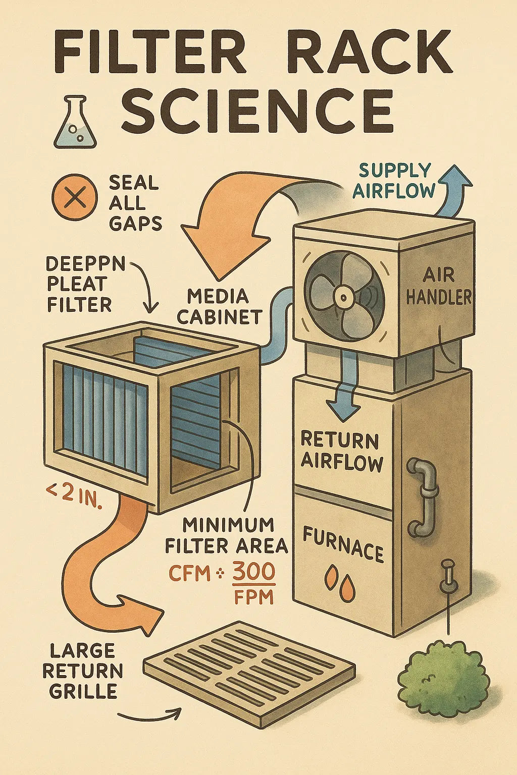
📐 5. Mike’s Filter Rack Sizing Formula (Simple + Accurate)
✔️ Rule 1:
Minimum 2 square feet of filter for every 1,000 CFM of airflow
✔️ Rule 2:
Preferred: 4 square feet of filter area per 1,000 CFM
✔️ Rule 3:
Deep-pleat beats flat-pleat every time
-
2-inch filters = good
-
4-inch filters = excellent
-
5-inch filters = best
✔️ Rule 4:
Face velocity should be under 300 feet per minute (FPM).
✔️ Rule 5:
Pressure drop must be under 0.10–0.15 inWC at system speed.
These rules dramatically reduce static pressure.
🔍 6. Comparing Filter Types in Real Systems
Mike performs real-world pressure testing on hundreds of homes.
Here are average pressure drops:
| Filter Type | Typical Pressure Drop | Notes |
|---|---|---|
| 1" pleated (MERV 8–11) | 0.20–0.30 inWC | Worst offender |
| 1" fiberglass | 0.08–0.12 inWC | Good airflow, poor filtration |
| 2" pleated | 0.12–0.16 inWC | Acceptable |
| 4" pleated | 0.06–0.12 inWC | Best blend of airflow + filtration |
| 5" media | 0.04–0.10 inWC | Premium airflow performance |
Mike almost always installs 4-inch or 5-inch media cabinets.
External Link: EPA on filtration and HVAC airflow
https://www.epa.gov/indoor-air-quality-iaq/air-cleaners-and-air-filters-home
🏗️ 7. Filter Rack Installation Mistakes Mike Fixes Every Day
This is where most systems fail—bad installation of the filter rack itself.
🪚 7.1 Warped or Bent Filter Rails
If the rails aren’t square:
-
filters leak
-
air bypasses filtration
-
dust coats the coil
-
pressure drop increases
Mike replaces rails with:
-
reinforced U-channels
-
gasketed rails
-
metal brackets
🧩 7.2 Gaps Around the Filter Rack
Gaps allow:
-
bypass air
-
coil fouling
-
pressure anomalies
Mike seals racks with:
-
foil tape
-
mastic
-
neoprene gasket
-
metal angles
🌀 7.3 Undersized Filter Grilles
If return grille area is too small:
-
pressure skyrockets
-
grille whistles
-
airflow collapses
Mike’s rule:
Grille free area must be 2× the filter face area.
🚫 7.4 Bottom-Facing Filter Slots Pull Dirt Off the Floor
Bottom slots act like vacuums for:
-
pet hair
-
dust
-
insulation fibers
-
dirt
These clog filters instantly.
Mike moves filter racks higher whenever possible.
📏 7.5 Filter Rack Installed on Wrong Side of Furnace
Return-side filter location matters.
Mike avoids:
-
sideways airflow
-
suction-side turbulence
-
bypass leaks
He installs filters in straight, laminar airflow.
🧬 8. How a Good Filter Rack Extends Equipment Life
Mike sees this repeatedly: Good filter racks increase equipment lifespan by 5–10 years.
Here’s why:
🌀 8.1 Blower Motor Runs Cooler
High static creates torque spikes.
Reduced static =
-
fewer ECM failures
-
lower watt draw
-
quieter operation
🔥 8.2 Furnace Heat Exchanger Runs Safer
More airflow =
-
lower temperature rise
-
fewer limit trips
-
longer heat exchanger life
External Link: Furnace safety and airflow
https://www.energy.gov/energysaver/furnaces-and-boilers
❄️ 8.3 Coil Stays Clean & Efficient
Cleaner coil =
-
higher heat transfer
-
better dehumidification
-
fewer freeze-ups
A dirty coil increases static by 0.20–0.40 inWC, worsening airflow exponentially.
💸 8.4 Lower Energy Consumption
Mike typically sees:
-
10–15% reduction in blower wattage
-
5–10% reduction in cooling energy
-
2–5% improvement in heating efficiency
🌬️ 8.5 Drastically Reduced System Noise
Lower static = quieter system.
Customers often say:
-
“My system sounds new.”
-
"It's like the blower isn't even running."
🔎 9. Case Study: Mike Fixes a Restrictive 1-Inch Rack
Home: 3,200 sq ft two-story
Equipment: 4-ton R-410A system
Static pressure: 0.82 inWC
Complaints:
-
loud ducts
-
hot upstairs
-
coil freezing
-
high humidity
-
short cycling
Mike’s Fixes:
-
replaced 1" rack with 4" media cabinet
-
upsized return grille
-
sealed air bypass leaks around old rack
-
tuned blower CFM
-
added second return
Results:
-
static pressure dropped from 0.82 → 0.47
-
system noise reduced ~50%
-
humidity dropped 10%
-
even room temperatures returned
-
coil freeze-ups eliminated
This is “filter rack science” in action.
🛠️ 10. Mike’s Official Filter Rack Build Formula (Step-by-Step)
Here is the exact method he uses.
🟦 Step 1: Measure System CFM Requirement
Based on:
-
furnace BTU
-
AC tonnage
-
duct design
-
system static rating
🟧 Step 2: Choose Filter Depth
-
<2 tons → 2" or 4"
-
2–4 tons → 4"
-
4 tons → 5"
🟥 Step 3: Size Filter Face Area
CFM ÷ 300 FPM = minimum filter face area.
🟩 Step 4: Install Media Cabinet
Mike uses metal cabinets with:
-
gasketed doors
-
zero bypass
-
rigid frames
🟨 Step 5: Seal Every Gap
No exceptions:
-
foil tape
-
mastic
-
gasket
-
screws
🟫 Step 6: Verify Static Pressure After Installation
Goal:
-
≤0.50 inWC total
-
≤0.15 across filter
Mike uses a manometer to test.
External Link: Static pressure testing
🎯 11. Mike’s “Filter Rack Science” Rules (Quick Summary)
✔️ Rule 1: The filter rack is the most common airflow choke point
✔️ Rule 2: 1-inch filters are obsolete for modern HVAC
✔️ Rule 3: Use 4–5" deep media filters whenever possible
✔️ Rule 4: Face velocity must stay under 300 FPM
✔️ Rule 5: Seal all bypass leaks
✔️ Rule 6: Oversized return grilles = lower static pressure
✔️ Rule 7: Test static pressure after every modification
✔️ Rule 8: Bigger filter → quieter system
✔️ Rule 9: Bigger filter → longer equipment life
✔️ Rule 10: Airflow first. Filtration second. Equipment third.
In that order.
🏁 Final Takeaway
Mike says it plainly:
“Most airflow problems start at the filter. Fix the rack, and the whole system starts breathing again.”
Filter Rack Science is the backbone of modern HVAC design.
Apply it, and you get:
-
lower noise
-
lower energy bills
-
stable coil performance
-
longer furnace life
-
better comfort
-
less dust
-
better humidity control
It’s one of the highest-value upgrades any homeowner or contractor can make.
Buy this on Amazon at: https://amzn.to/47z1067
In the next topic we will know more about: High-Velocity Problem Solving: Mike’s Fixes for Homes Where the 4-Ton System Overpowers the Layout

