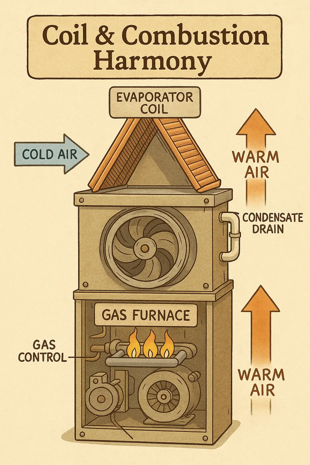
In most homes, the furnace and evaporator coil sit right on top of each other, stacked like pancakes. Simple, right?
Not if you want the system to run safely, efficiently, and without noise, short-cycling, coil sweat, or heat-induced airflow restrictions.
Mike Sanders has a rule he teaches in every training session:
“If your coil and furnace aren’t tuned to each other, the whole system fights itself.”
This is especially true when pairing a vertical evaporator coil with a high-output 80% AFUE gas furnace, like the 100k–120k BTU models commonly installed in large homes.
The coil affects the furnace. The furnace affects the coil.
And if they aren’t synchronized, you end up with:
-
overheating
-
cold-blow complaints
-
furnace limit trips
-
loud airflow
-
long AC recovery times
-
poor humidity removal
-
coil freeze-ups in summer
-
cracked heat exchangers over time
This guide gives you Mike’s full blueprint for achieving coil & combustion harmony — a perfect synchronization of airflow, heat rise, coil load, and blower tuning that results in a quiet, efficient, stable system.
🧠 1. Why Coil-Furnace Synchronization Matters So Much
At first glance, the furnace and coil look like two separate pieces of equipment.
They are not.
They share:
-
the same blower
-
the same return duct
-
the same supply plenum
-
the same static pressure environment
-
the same airflow limitations
Most homeowners — and even many installers — don’t realize how tightly integrated these components are.
To Mike, they’re part of the same machine.
🔥 1.1 The Furnace Generates Heat — But the Coil Controls Back-Pressure
A vertical evaporator coil sits directly in the furnace’s path of heated air.
That means the coil:
-
resists airflow
-
adds static pressure
-
affects temperature rise
-
impacts combustion stability
The hotter the furnace output, the more resistance the coil creates.
High BTU furnaces and restrictive coils do not mix unless tuned properly.
❄️ 1.2 The Coil Controls AC Efficiency — But Relies on Furnace Airflow
In cooling season, the furnace’s blower becomes the AC blower.
Its ability to:
-
hit target CFM
-
maintain static pressure
-
stay below low-temperature limits
determines whether the coil stays cold without freezing.
A coil starved of airflow becomes:
-
too cold
-
too moist
-
prone to icing
-
unable to dehumidify the home
So heating airflow and cooling airflow are tightly bound.
⚙️ 1.3 High-Output 80% Furnaces Demand More Airflow Than AC Loads
A 120k BTU furnace may need 1800–2200 CFM, while the AC coil may only need 1400–1600 CFM.
If the ductwork or blower tuning favors cooling airflow, the furnace overheats.
If it favors heating airflow, the coil can flood or freeze.
Thus, synchronization is mandatory.
External Link: Furnace temperature rise fundamentals
https://www.energy.gov/energysaver/furnaces-and-boilers
🧩 2. The Four Interactions Between a Vertical Coil & 80% Furnace
Mike teaches four behavior patterns that determine system harmony.
🔥📈 2.1 Interaction #1: Temperature Rise vs. Coil Restriction
Every furnace has a rated temperature rise, usually:
-
35–65°F (typical for 80% furnaces)
If airflow is too low because the coil is restrictive, temperature rise skyrockets.
This causes:
-
limit switch trips
-
short cycling
-
overheated exchangers
-
reduced blower life
Target:
✔️ Keep rise inside manufacturer spec
✔️ Target the middle of the rise range for long furnace lifespan
🌬️💨 2.2 Interaction #2: Static Pressure vs. Coil Surface Area
Vertical coils can be:
-
A-coil
-
N-coil
-
Slab coil (rare)
The larger the coil surface area, the lower the resistance — usually.
But some high-efficiency coils are dense with fins and tubing, increasing restriction.
Static pressure directly affects:
-
blower speed
-
airflow volume
-
heat exchanger temperature
Target:
✔️ Total external static pressure ≤ 0.5 inWC
✔️ Never exceed 0.8 inWC or equipment life drops dramatically
❄️🧊 2.3 Interaction #3: Coil Flooding vs. Furnace Blower Speed
If blower speed is too high:
-
coil moisture removal drops
-
coil temperature split shrinks
-
home feels humid
If blower speed is too low:
-
coil gets too cold
-
refrigerant floods
-
coil freezes
This requires seasonal blower tuning, something Mike does automatically.
External Link: AC coil performance basics
https://www.energy.gov/energysaver/central-air-conditioning
🔥🌀 2.4 Interaction #4: Furnace Combustion vs. Airflow Path Turbulence
Combustion stability depends on consistent heat removal from the heat exchanger.
Bad coil alignment creates turbulence, which causes:
-
inconsistent rising air patterns
-
hot pockets
-
unstable flame patterns (rare but real)
-
nuisance limit trips
Thus, coil alignment is not cosmetic — it’s thermal engineering.
🛠️ 3. Mike’s Coil & Combustion Harmony Checklist
This is Mike’s full synchronization framework.
📏 3.1 Step 1: Verify Coil Type, Tonnage & Orientation
Mike checks:
-
coil tonnage
-
coil static rating
-
coil cabinet width to match furnace
-
coil offset and alignment
-
A-coil vs N-coil pressure profile
📘 Coil selection rules:
-
A-coil = lower pressure drop, better harmonization with 80% furnaces
-
N-coil = high efficiency but higher restriction; must correct static pressure
-
Coil tonnage must be equal to or greater than system tonnage
External Link: AHRI matched system guidelines
https://www.ahridirectory.org
🔄 3.2 Step 2: Match Furnace Blower to Coil Requirements
Mike checks blower CFM tables, then sets:
✔️ High heat stage CFM
✔️ Low heat stage CFM
✔️ Cooling CFM
✔️ Dehumidification mode (if ECM blower)
He tunes blower speed based on:
-
coil wet performance
-
temperature rise targets
-
static pressure
-
duct capacity
This step alone eliminates 50% of furnace/coil conflicts.
🧱 3.3 Step 3: Ensure Proper Coil Positioning (Vertical Coil Best Practices)
Mike checks:
🟦 3.3.1 The Coil Sits Fully Centered Over the Furnace
Misaligned coils cause:
-
turbulence
-
heat pockets
-
coil sweat
-
premature rust
🟦 3.3.2 The Coil Pan Must Be Below Load-Bearing Rails
A sagging coil pan floods the furnace vestibule.
🟦 3.3.3 The Coil Must Have Correct Pitch
Forward pitch of ¼" ensures drainage.
🔥 3.4 Step 4: Temperature Rise Testing (The Make-or-Break Step)
Mike tests:
-
supply air temp
-
return air temp
-
mid-plenum temp
Then calculates temperature rise:
Rise = Supply Temp – Return Temp
Target range:
✔️ Middle of furnace spec
✔️ Usually 45–55°F
Too high = coil too restrictive
Too low = blower too fast or bypassing coil
This ensures combustion heat is properly absorbed.
🌀 3.5 Step 5: Static Pressure Testing
Mike tests:
-
return static
-
supply static
-
total external static pressure
Targets:
✔️ ≤ 0.50 inWC total
✔️ Return side ≤ 0.20
✔️ Supply side ≤ 0.30
If static is high:
-
enlarge return duct
-
increase filter size
-
fix sagging flex
-
add additional returns
-
enlarge critical supply branches
External Link: Duct performance basics
💧 3.6 Step 6: Condensate & Coil Drainage Optimization
Mike ensures:
-
proper trap height
-
anti-float checks for coil pan
-
correct slope for drain lines
-
secondary drain protection
Improper drainage leads to:
-
coil freeze
-
musty odors
-
overflow safety shutoff trips
🔧 3.7 Step 7: Seasonal Mode Synchronization
Mike sets two blower profiles:
Summer Mode:
-
lower CFM for better dehumidification
-
tighter temperature split
-
reduced coil flood risk
Winter Mode:
-
higher CFM for heat rise control
-
faster warm-up
-
furnace protection
This dual-profile approach is the secret to perfect harmony.
📐 4. Furnace-to-Coil Airflow Sizing: Mike’s Golden Ratios
These ratios eliminate 90% of system conflicts.
🟦 4.1 80% Furnace Output vs. Coil Tonnage
For a 120k BTU furnace:
-
3.5–4 ton coil = ideal pairing
-
2–3 ton coils = overly restrictive
-
5 ton coil = low velocity, poor dehumidification
🟥 4.2 Furnace Output vs. Blower CFM
Mike targets:
-
400 CFM/ton for cooling
-
20–30% more for heating
-
Add 10% extra if ducts include long flex runs
🟩 4.3 Filter Sizing Rules
Mike’s minimum rules for a 120k furnace:
-
2" filter = 2000 CFM max
-
4" filter = 2200+ CFM max
-
Filter grille area = 2–4 sq ft minimum
1" filters are almost always too restrictive.
🟧 4.4 Coil Pressure Drop Compensation
If coil has high fin density:
-
open additional returns
-
increase trunk size
-
change blower tap
-
upsize key duct runs
🛠️ 5. What Happens When Coil & Furnace Are NOT in Harmony?
Mike sees certain failures repeatedly.
❌ 5.1 Furnace Trips High-Limit Switch
Most common failure.
Caused by:
-
coil too restrictive
-
blower too slow
-
duct system undersized
❌ 5.2 Coil Sweating or “Raining” on Furnace
Warm furnace air meets cold coil pan.
Caused by:
-
rapid cycling
-
short blower off-delay
-
coil misalignment
❌ 5.3 Loud Airflow or Whistling
Static pressure too high.
❌ 5.4 AC Freeze-Ups
Blower tuned too low for the coil.
❌ 5.5 Furnace Heat Exchanger Overstress
This shortens furnace lifespan dramatically.
🧱 6. Real-World Example: Mike Fixes a Bad Furnace-Coil Match
Home: 2,400 sq ft
Equipment: 4-ton coil + 120k 80% furnace
Symptoms:
-
AC freeze-ups
-
furnace overheating
-
loud airflow
-
high humidity
-
short cycling
What Mike Found:
-
coil offset ¾" off center
-
static pressure 0.82 inWC
-
return undersized
-
1" filter rack
-
blower set too high for cooling
Mike’s Fixes:
-
centered coil
-
installed 4" media filter
-
added 2nd return
-
reduced blower speed in cooling
-
increased heat-stage CFM
-
upsized two flex runs
Final Results:
-
static pressure: 0.82 → 0.47
-
furnace stabilized
-
AC stopped freezing
-
humidity decreased
-
airflow noise cut in half
-
comfort dramatically improved
This is coil & combustion harmony in action.
🎯 7. Final Takeaway
Mike sums it up perfectly:
“Your furnace and coil don’t work in isolation — they speak the same airflow language. My job is to make sure they’re speaking it clearly.”
Synchronizing a vertical evaporator coil with a high-output 80% furnace is the difference between:
-
a loud, inefficient system
-
and a quiet, high-performance home comfort machine
When coil, combustion, airflow, and static pressure are all in harmony, the system becomes stable, efficient, and long-lasting — exactly as it should be.

