Newsletter Subscribe
Enter your email address below and subscribe to our newsletter

HVAC made simple
By Jake Lawson | HVAC Specialist | The Furnace Outlet | Updated November 2026
If you’ve recently installed a Goodman GLXS4BA3610 central air conditioner with an AMST36CU1300 air handler, you may be wondering how to configure the blower settings for proper cooling performance. It’s an important question because even a correctly sized air-conditioning system can struggle when the indoor blower delivers too much or too little airflow. Incorrect airflow can contribute to poor humidity removal, uneven temperatures, excessive noise, frozen evaporator coils, and unnecessary equipment wear. It can also affect the refrigerant system’s operating conditions, making a properly charged air conditioner appear to have a different problem.
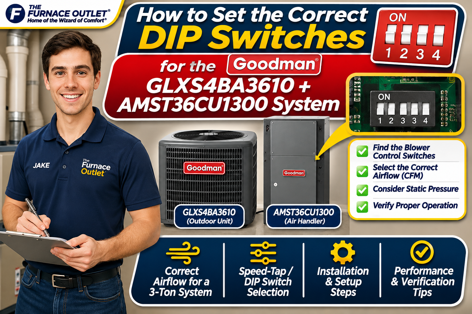
One detail needs clarification before we begin: the AMST36CU1300 should not automatically be treated like older Goodman air handlers that use banks of numbered DIP switches. The AMST U1300 equipment documentation describes selectable blower speed taps, and the correct adjustment method depends on the installed control-board and motor configuration.
This guide explains how the Goodman GLXS4BA3610 and AMST36CU1300 work together, how to determine the appropriate cooling airflow, where to find the applicable speed-selection instructions, and how a qualified technician should verify the final configuration. The objective is not to recommend a universal switch position. It’s to help homeowners and installers understand the manufacturer-approved process for setting up this specific three-ton R-32 cooling system.
The Goodman GLXS4BA3610 is a nominal three-ton split-system air conditioner designed for R-32 refrigerant. It belongs to Goodman’s GLXS4B equipment family and is intended to operate with an approved indoor coil or air handler. The AMST36CU1300 is a nominal three-ton, multi-position air handler featuring an electronically commutated blower motor and an indoor evaporator coil designed for compatible R-32 applications.
Together, these components form a conventional residential split cooling system. The outdoor condenser provides refrigeration, while the indoor air handler circulates conditioned air through the home’s ductwork. Unlike some premium communicating systems, this combination should not be assumed to automatically determine the ideal blower airflow from the outdoor condenser model alone.
The installer must confirm the approved equipment match, select the appropriate indoor airflow setting, and verify actual performance under operating conditions. The manufacturer documentation is especially important because control configurations can differ between Goodman air-handler families and production revisions.
A DIP switch is a small mechanical switch mounted on an electronic circuit board. HVAC manufacturers sometimes use groups of these switches to configure blower airflow, electric heat capacity, dehumidification, and operating profiles. However, not every Goodman air handler uses this arrangement. Older Goodman AVPTC and certain other ECM blower platforms use numbered DIP switches for airflow selection. Those switches may control cooling speed, airflow adjustments, comfort profiles, and electric heating settings.
The AMST U1300 family uses a different setup approach described in its installation documentation under speed-tap adjustment. Consequently, an AVPTC DIP-switch chart should not be copied onto an AMST36CU1300. Before changing anything, the technician should identify the actual control-board markings, motor speed-selection arrangement, and installation manual corresponding to the equipment’s complete model and revision. If the installed unit has no numbered DIP-switch bank, that is not necessarily a missing component or installation defect. It may simply use a different method of selecting blower airflow.
Central air conditioners are commonly configured around approximately 350–400 cubic feet per minute (CFM) of indoor airflow per nominal ton of cooling capacity, although the correct value depends on the equipment and installation. For a three-ton system, that general range corresponds to approximately 1,050–1,200 CFM.
This is a starting point for understanding airflow, not a manufacturer-approved universal setting. The AMST U1300 installation instructions specifically direct technicians to select the cooling or heat-pump speed tap according to the applicable AHRI rating. Where that information is unavailable, the manual calls for a minimum of 350 CFM per outdoor ton.
For the GLXS4BA3610, that minimum calculation is 3 × 350, or 1,050 CFM. However, the technician must also consider external static pressure, duct resistance, equipment orientation, and any restrictions identified in the manufacturer’s airflow tables. Choosing a nominal 1,200-CFM setting does not guarantee that the system will actually deliver 1,200 CFM through the installed ductwork.
External static pressure represents the resistance the blower encounters while moving air through the external duct system and associated components. When ductwork is undersized, filters are restrictive, return-air pathways are inadequate, or supply registers are obstructed, static pressure can increase. As resistance rises, actual airflow may decrease, depending on the blower motor’s operating characteristics and selected speed.
This is why technicians should not select a blower speed based on system tonnage alone. The AMST installation manual provides airflow information at different external static pressure conditions. The technician must compare the measured system pressure with the applicable airflow table and confirm that the installation remains within the unit’s rated operating limits.
Increasing blower speed to compensate for restrictive ductwork may increase noise and power consumption without resolving the underlying airflow problem. A properly configured system requires both the appropriate blower selection and an adequately designed duct system.
The first step is to confirm the complete air-handler model number from the equipment nameplate. The technician should also record the serial number and identify the installed motor and control-board revision. Next, the installer should obtain the corresponding AMST U1300 installation and operating instructions rather than relying on a generic Goodman blower setup chart.
The manual’s speed-tap adjustment section explains the applicable selection method, while the airflow tables show how blower performance changes with static pressure. The correct speed tap is determined by the required cooling airflow and the measured external static pressure, not simply by choosing the highest available speed. Before accessing internal electrical components, all power sources must be disconnected and verified de-energized by a qualified technician. Air handlers may have separate power supplies associated with optional electric heat kits, and internal electrical components can remain hazardous.
Once the correct selection has been established, the technician can make the manufacturer-approved adjustment and document the original and final configuration. Homeowners should not move internal speed-selection connections or switches themselves, because an incorrect adjustment can compromise cooling performance and electrical safety.
For the Goodman GLXS4BA3610 and AMST36CU1300 combination, the appropriate procedure begins with identifying the equipment’s required cooling airflow from its certified match and manufacturer documentation. The technician should then measure total external static pressure using appropriate instruments and compare the results with the AMST36CU1300 airflow performance table.
After identifying the speed tap capable of providing the required airflow within the equipment’s operating limits, the technician can configure the blower using the method specified for that particular motor and control assembly.
The system should then be operated under normal cooling conditions while airflow, temperature difference, refrigerant operating conditions, and electrical performance are evaluated. If the measured airflow differs substantially from the expected value, the installer should investigate duct restrictions, filter pressure drop, return-air sizing, and other possible causes before making further adjustments.
The important point is that the correct blower setting is verified through measurements rather than selected by guesswork.
One common source of confusion is the availability of older Goodman service manuals showing switch banks labeled S1 through S13. Those instructions may be correct for the specific AVPTC or other air-handler families they describe, but they are not automatically applicable to the AMST36CU1300. For example, an older Goodman control board may use separate switches for cooling airflow, airflow trim, dehumidification, and electric heating. The AMST U1300 documentation describes speed-tap selection instead.
Using the wrong control diagram could lead to incorrect blower operation, unexpected heating behavior, or interference with the equipment’s safety functions. The safest approach is to match every setup instruction to the exact model number and control-board revision.
The AMST36CU1300 may be installed with compatible optional electric resistance heating equipment. If an electric heat kit is present, the installer must consider its airflow and electrical requirements separately from the cooling system’s needs.
Electric heat elements require sufficient airflow to operate safely. Incorrect blower configuration can contribute to overheating, high-limit control operation, or equipment damage. The appropriate heat-kit installation instructions must therefore be reviewed alongside the air-handler documentation.
A cooling-only installation should not be configured as though a particular electric heater were present, and a system with electric heat should never have its heating airflow requirements ignored. Any adjustment involving electric heat wiring, heater capacity, or blower control should be completed by a qualified HVAC technician.
The GLXS4BA3610 and AMST36CU1300 combination uses R-32, an A2L refrigerant classified as mildly flammable. Compatible indoor equipment may incorporate refrigerant detection and mitigation functions intended to respond to specified leak conditions. The AMST36CU1300 is listed with a factory-installed R-32 mitigation device. Its installation documentation also identifies minimum mitigation airflow and conditioned-space requirements.
These safety-related airflow values should not be confused with the normal cooling airflow target. For example, the AMST36CU1300 documentation identifies a mitigation-mode minimum circulation airflow of approximately 380 CFM, which is substantially below the normal cooling airflow requirement for a three-ton system.
That mitigation value serves a different purpose and must not be used as the standard cooling blower setting. Technicians must preserve the manufacturer’s refrigerant safety controls and verify that any blower adjustment remains compatible with the system’s required mitigation operation.
A blower operating below the required airflow may contribute to weak supply airflow, poor cooling distribution, reduced evaporator temperature, and potentially frozen coils. An excessively high blower setting may create objectionable duct noise and reduce moisture-removal effectiveness under certain conditions.
However, these symptoms do not prove that the speed tap is incorrect. Similar problems can result from dirty filters, duct restrictions, improper refrigerant charge, thermostat issues, or mechanical faults.
For this reason, adjusting blower speed should not be the first response to every cooling complaint. A technician should inspect the system, measure airflow-related conditions, and rule out other problems before changing the configuration.
What DIP-switch positions should I use for the Goodman AMST36CU1300? There is no verified universal numbered DIP-switch combination for this model. The AMST U1300 documentation describes speed-tap adjustment, and the correct configuration depends on the required airflow, external static pressure, and installed control assembly.
What airflow does the GLXS4BA3610 require? A common three-ton cooling airflow range is approximately 1,050–1,200 CFM. The AMST documentation specifies selecting the tap according to the AHRI rating, or at least 350 CFM per outdoor ton when that rating information is unavailable. The exact approved setting must be verified.
Can I increase the blower speed to improve cooling? Increasing airflow does not necessarily improve cooling performance. Excessive airflow may reduce humidity removal or increase noise, while insufficient airflow can create other problems. The correct setting should be established through manufacturer data and system measurements.
Does the outdoor Goodman condenser have blower DIP switches? The indoor air handler controls indoor blower operation. The GLXS4BA3610 outdoor unit’s wiring and controls serve different functions and should not be confused with the indoor airflow-selection arrangement.
Can the factory blower setting be left unchanged? Possibly, but factory settings should not be assumed correct for every installation. The installer should verify airflow against the certified equipment combination and actual duct conditions.
When homeowners ask me which DIP switches to set on a Goodman GLXS4BA3610 and AMST36CU1300 system, my first recommendation is to identify the exact indoor blower control. The AMST U1300 family should not be configured using an unrelated Goodman AVPTC DIP-switch chart.
For this three-ton system, approximately 1,050–1,200 CFM provides a useful initial reference, but the final target and speed selection must follow the appropriate equipment documentation. I would have the installer verify the certified equipment match, measure external static pressure, consult the AMST airflow table, and document the selected speed tap. I’d also confirm that any installed electric heat and R-32 safety functions operate as intended.
The goal isn’t to make the blower run as fast as possible. It’s to deliver the correct airflow safely and consistently so the entire cooling system performs as designed.
Goodman AMST U1300 Installation and Operating Instructions: AMST R-32 Installation Manual. Provides the speed-selection procedure, airflow performance tables, static-pressure considerations, and refrigerant mitigation requirements.
Goodman GLXS4B Product Specifications: GLXS4B R-32 Technical Documentation. Covers condenser specifications, wiring information, and applicable equipment details.
AMST U1300 Manual Reference: AMST U1300 Airflow Requirements. Includes airflow selection notes, installation-orientation adjustments, and mitigation-mode requirements.
Complete Goodman System Documentation: GLXS4BA3610 + AMST36CU1300 Equipment and Manuals. Provides access to model-specific specifications and installation documents.