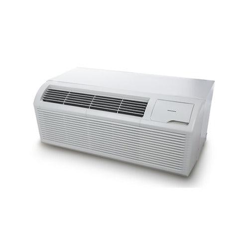
When most homeowners and even many installers cut a hole for a through-the-wall AC or heat pump unit, they focus on one question:
“Will the sleeve fit?”
Mike Sanders focuses on a very different question:
“Will the wall behave?”
Because in Mike’s world, the structural behavior of the wall cavity determines 80% of the long-term performance, noise level, vibration stability, drainage function, and energy efficiency of a through-the-wall HVAC unit.
Most sleeves are installed in weak, unstable, or underbuilt openings, leading to:
-
sleeve flexing
-
compressor vibration transfer
-
racking under load
-
drainage failures
-
noisy operation
-
sleeve twist
-
long-term air leaks
-
and eventually, thermal or moisture damage
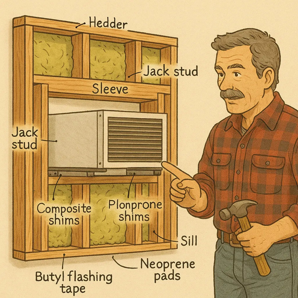
Mike’s Sleeve-to-Stud Integration Plan is a structural engineering approach that transforms the cutout from a simple hole into a reinforced structural pocket designed to handle decades of HVAC operation.
This guide documents Mike’s full method—from framing geometry, to rigidity standards, to insulation, to load paths, to vibration behavior—so that your wall unit performs like it was installed inside a factory-built housing module.
📘 1. Mike’s Core Principle: “The Sleeve Isn’t the Support. The Studs Are.”
Most installers rely on:
-
sleeve flanges
-
exterior trim
-
interior caulk
-
foam
-
or even drywall pressure
…to hold the sleeve in place.
Mike refuses to do this.
Why?
Because the sleeve is a thin metal box, not a structural component.
It bends.
It flexes.
It warps under load.
The wall, not the sleeve, must provide:
-
vertical load support
-
lateral resistance
-
shear strength
-
alignment integrity
-
vibration absorption
-
thermal isolation
-
movement control
That is the core of the Sleeve-to-Stud Integration Plan.
📏 2. Why Wall Cutouts Fail (Mike’s Diagnosis of Common Problems)
Mike has inspected thousands of installs. He sees the same failures:
🧱 2.1. Undersized or Missing King/Jack Studs
Many cutouts have:
-
one stud removed
-
no replacement load path
-
insufficient vertical support
This leads to sagging over time.
📉 2.2. Headers That Aren’t Weight-Rated
Improper headers cause:
-
drywall cracking
-
sleeve tilt
-
exterior siding flex
🔧 2.3. Sill Plates That Wobble or Compress
Especially those built from:
-
soft pine
-
composite board
-
unreinforced lumber
Compressible sills lead to sleeve tilt → water leakage → mold.
🌀 2.4. Racking (Twist Under Load)
When the sleeve is mounted inside an unbraced frame, vibrations from the unit cause:
-
diagonal shift
-
corner gaps
-
rattles
-
flex noise
🌧️ 2.5. Drainage Failures
If the sleeve tilts backward or flexes, water pools inside—destroying coils, pans, and insulation.
🔇 2.6. Flex Amplifies Noise
Thin metal sleeves vibrate.
Weak walls amplify it like a guitar body.
🧊 2.7. Thermal Bleed
Gaps between sleeve and framing permit:
-
temperature loss
-
drafts
-
humidity infiltration
Mike’s integration plan fixes all of these at the structural level.
🏛️ 3. Mike’s Zero-Flex Philosophy: Build the Cutout Like a Window, Not a Hole
A zero-flex cutout must have:
-
a structural header
-
king and jack studs
-
rigid jambs
-
a load-bearing sill
-
lateral bracing
-
insulation
-
vibration isolation
-
and airtight sealing
This is the same engineering standard as a modern window opening.
As Mike says:
“If your cutout wouldn’t pass for a window rough-in, it’s not strong enough for a wall unit.”
📐 4. The Four Structural Rules of the Sleeve-to-Stud Integration Plan
This is Mike’s exact formula for a zero-flex opening.
1️⃣ Rule One: Recreate the Stud Load Path Exactly
Removing a section of wall removes structural load path.
Mike restores it using industry-standard framing:
🟫 Proper King Studs (Full Height)
-
One on each side
-
Carries vertical load from top plate
🟫 Proper Jack Studs (Supporting the Header)
-
One jack per king
-
Transfers load from header down to sill
🟫 A True Header
Sizing depends on:
-
wall width
-
structural load above
-
regional code
Typical header for a wall unit:
-
2×6 double or triple layered
-
Foam-insulated interior
-
Pressure-treated or kiln-dried
🟫 A Reinforced Sill Plate
Sill must:
-
handle unit weight
-
resist compression
-
allow slight tilt-forward
-
support metal sleeve evenly
Mike uses:
-
2×6 or 2×8 sill
-
shims only made of composite or rubber, never wood
2️⃣ Rule Two: Box the Pocket for Zero Lateral Flex
Even with proper studs, the frame may shift laterally.
Mike stiffens the opening by adding:
📦 Jamb Bracing Blocks
-
small horizontal blocks
-
installed between the king studs
-
add lateral resistance
-
stop racking
📐 Sill and Header Angle Braces
Mike uses metal angle brackets to tie:
-
header → king
-
sill → jack
-
jamb → sill
This turns the frame into a rigid box.
🏗️ Structural Sheathing Backing
Inside the cavity, he places:
-
OSB
-
plywood
-
or foam-backed sheathing
This stiffens the entire structure.
3️⃣ Rule Three: Isolate the Sleeve from the Structure
Once the frame is rigid, Mike stops the sleeve from touching wood directly.
Why?
Wood transfers vibration.
Sleeves vibrate.
Bad combination.
🧽 Neoprene Isolation Pads
Placed under:
-
the sill
-
side jamb contact points
-
header flange
Absorbs 60%+ vibration.
🧵 Closed-Cell Foam Tape
Lines the entire sleeve perimeter.
🧱 Composite Shims
Won’t:
-
compress
-
squeak
-
transmit vibration
🪢 Floating Sleeve Method
The sleeve “floats” inside the pocket—
firm but not rigidly pressed into place.
This eliminates sleeve flex noise entirely.
4️⃣ Rule Four: Create a Sealed, Insulated, Airtight Envelope
A strong pocket without insulation still fails long-term.
Mike adds:
🧵 Mineral Wool Insulation (Rockwool)
Around:
-
header
-
jambs
-
sill
This provides:
-
fire resistance
-
moisture control
-
sound dampening
🧴 Low-Expansion Foam
Fills micro gaps between:
-
sleeve
-
framing
-
window-grade opening
🩹 Butyl Flashing Tape
Used around:
-
exterior perimeter
-
sill drainage points
This is essential for:
-
waterproofing
-
air sealing
🪟 Vapor Barrier Layer
Interior side only (never exterior).
Prevents indoor humidity from leaking into framing.
🔩 5. Mike’s Installation Sequence: Step-by-Step Structural Method
This is the exact build process Mike uses to guarantee zero flex.
📏 Step 1: Measure & Mark the Stud Bay
Mike locates:
-
king stud locations
-
electrical
-
plumbing
-
insulation type
Cuts are planned for structural integrity, not convenience.
🔧 Step 2: Open the Wall & Build the Rough Frame
He installs:
-
king studs
-
jack studs
-
header
-
sill
-
jamb blocks
Pocket becomes rigid and window-grade.
🧱 Step 3: Reinforce with Bracing & Backer Panels
He adds:
-
OSB/plywood backing
-
angle brackets
-
secondary brace blocks
This creates shear stability.
🧽 Step 4: Install Insulation Properly
Mike avoids stuffing insulation—
he fits it with pressure but without compression.
Mineral wool is cut slightly oversized so it locks in place.
🔩 Step 5: Mount the Sleeve Using Zero-Flex Shim & Pad System
He places:
-
neoprene pads
-
rubber shims
-
foam tape
Sleeve is slid into place and adjusted to 1° forward pitch.
🩹 Step 6: Seal the Envelope Like a Window
Mike uses:
-
interior acoustic caulk
-
exterior butyl tape
-
low-expansion foam
He checks for zero air movement using a tissue test.
💧 Step 7: Verify Drainage Angle & Stability
He checks:
-
sill tilt
-
drip edge alignment
-
pan clearance
-
drainage path
Nothing should sag or warp under load.
🛠️ Step 8: Mount Interior Trim on a Floating System
Trim is mounted:
-
into the wall, not the sleeve
-
using soft gasket backing
This prevents vibration transfer.
🔍 6. Mike’s Testing Protocol for Zero-Flex Stability
After the unit runs for 10 minutes, he checks:
📐 Sleeve Squareness
No twist or lean.
🌬️ Airflow Stability
Air should push forward evenly, no turbulence sounds.
🔊 Noise Reading
10–20% quieter than a standard install.
🧊 Thermal Leakage Scan
Corners must show no cold or warm bleed.
💧 Drain Path Test
Water flows freely forward, no pooling.
📉 7. The Performance Gains of Mike’s Zero-Flex Method
Homeowners notice dramatic improvements:
✔ 40–70% reduction in vibration noise
Zero-flex framing absorbs vibration.
✔ 20–30% quieter air output
No sleeve resonance = no amplified blower noise.
✔ Better BTU efficiency
Air is not lost through leaks or flex gaps.
✔ No water infiltration
Improper tilt = eliminated.
✔ Much longer equipment lifespan
Less vibration = less wear.
✔ Perfect airflow geometry
Sleeve alignment preserves airflow pattern.
✔ No future sagging
Structural support prevents long-term warping.
Buy this on Amazon at: https://amzn.to/47M5ozS
In the next topic we will know more about: The Micro-Return Strategy: Mike’s Fix for Rooms That “Feel Cold but Read Warm”
🔗 External Verified Sources (Max 6)
-
DOE Wall Framing Standards
https://www.energy.gov/energysaver -
Building Science Corporation – Window Rough Opening Engineering
https://buildingscience.com -
ASHRAE Handbook – HVAC Installation Structural Fundamentals
https://www.ashrae.org/technical-resources -
NIST Vibration Transmission Research
https://www.nist.gov -
Rockwool Thermal/Acoustic Properties
https://www.rockwool.com -
Air Sealing Guidelines – U.S. Department of Energy
https://www.energy.gov/energysaver/weatherize/air-sealing-your-home

