Whenever somebody tells me “My room doesn’t feel right”, the first thing I ask is:
“Show me your airflow diagram.”
Most folks just stare back.
Because here’s the truth:
Almost nobody draws airflow before installing HVAC equipment — but every professional SHOULD.
A PTAC, mini split, heat pump, or packaged AC will only perform as well as the circulation in the room allows. If the air gets trapped, loops back too soon, hits obstacles, or forms stagnant pockets, even the most advanced unit will struggle.
So I created a system called the Comfort Flow Diagram — a simple sketching process that uses arrows, lines, and room geometry to determine exactly how air should move before anything gets installed.
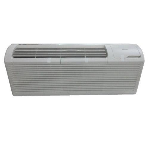
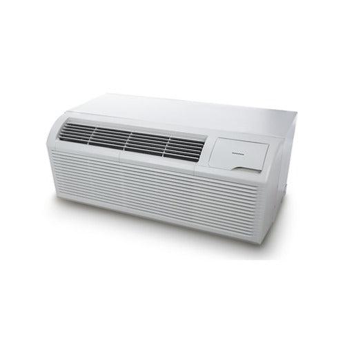
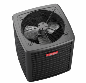
Amana Distinctions Model 12,000 BTU PTAC Unit with 3.5 kW Electric Heat
This isn’t advanced engineering.
This is Mike’s simple, field-tested way to eliminate hot corners, cold walls, dead zones, and “my AC is on but I don’t feel it” problems.
Let’s build your Comfort Flow Diagram step-by-step.
📄 1. What a Comfort Flow Diagram Actually Is (and Why It Works)
A Comfort Flow Diagram is a quick, visual map of:
-
Where conditioned air enters
-
Where it should travel
-
How it circulates
-
Where it exits or returns
-
What obstacles distort that flow
Think of it like the “flight path” of air.
Instead of guessing where a PTAC or mini split belongs, you draw the airflow first, then choose equipment placement.
This ensures:
✔️ Even temperature throughout the room
✔️ No hot or cold zones
✔️ No stale corners
✔️ Proper thermostat readings
✔️ Correct BTU performance
✔️ Real-world comfort, not just “technical” output
🖊️ 2. The Tools You Need to Draw It (2 Minutes of Prep)
You don’t need architectural software.
Mike’s kit is simple:
✔️ A notepad or printer paper
✔️ A pencil or marker
✔️ A laser measure (for accurate room dimensions)
✔️ Painter’s tape (to mark live airflow tests)
✔️ An anemometer (optional but helpful)
✔️ IR thermometer (to validate hot/cold zones)
You can find a recommended IR thermometer here.
📐 3. Step One — Draw the Room Shape (Never Skip This)
Sketch the room as a simple box.
Then add:
-
Windows
-
Doors
-
Hall openings
-
Closets
-
Furniture that can’t be moved
-
Ceiling height notes
-
Any obstructions
This gives you the “canvas” for airflow design.
Important note:
The shape matters.
A 10×16 room behaves NOTHING like a 12×12 room, especially for PTAC airflow.
🌞 4. Step Two — Identify Thermal Zones Before Drawing Air
Before sketching airflow, mark:
🔥 Hot zones
-
South/west windows
-
Large glass areas
-
Electronics
-
Poor insulation areas
❄️ Cold zones
-
Exterior-facing corners
-
Leaky windows
-
Poorly insulated walls
Use a thermal scanner or IR thermometer to confirm.
Reference: DOE insulation basics
https://www.energy.gov/energysaver/weatherize/insulation
Mark these zones on your diagram in red (hot) and blue (cold).
🌀 5. Step Three — Draw the “Primary Air Path”
Now the magic begins.
Every HVAC unit produces a primary airflow direction, also called the “throw path.”
For PTACs, the airflow is horizontal — straight out.
For mini splits, it’s angled downward.
For air handlers, it depends on the register.
Mike’s Rule:
Aim the primary airflow toward the longest dimension of the room.
So draw a big arrow from the unit’s location toward:
➡️ the farthest corner
➡️ the center of the room
➡️ the opposite wall
This gives air “runway” to circulate.
Never aim air:
✖️ Toward the bed headboard
✖️ At a wall 3 feet away
✖️ Into a dead-end hallway
✖️ Directly up toward a ceiling beam
Those dead-end pathways ruin circulation.
🔄 6. Step Four — Add the “Return Path Arrow”
PTACs don’t have a return duct, but rooms still have natural return pathways.
Mark where air LEAVES the room:
-
A doorway
-
A hallway
-
A stairwell
-
An open entry
Draw a large arrow pointing toward that exit.
Air must enter AND leave, or circulation dies.
Rooms with no return pathway develop:
-
Hot ceilings
-
Cold floors
-
Stagnant corners
-
Short cycling
If the return path isn’t obvious, create it:
-
Under-door gap
-
Transfer grille
-
Leaving the door slightly open
🔺 7. Step Five — Add Mike’s “Tri-Zone Flow Pattern”
This is the signature technique I use on every job.
Good airflow connects three zones:
-
The launch zone
Where conditioned air begins -
The travel zone
Middle of the room where mixing happens -
The exit zone
Where air leaves and circulation restarts
Draw three arrows forming a big loop.
This loop ensures:
✔️ Even mixing
✔️ Stable thermostat readings
✔️ Balanced temperature
✔️ No backflow toward the unit
You want your diagram to show a loop, not a straight blast of air.
🚫 8. Step Six — Identify Obstacles (and Fix Them Before Install)
Now circle anything that blocks airflow:
-
Tall bookshelves
-
Bed frames
-
Angled walls
-
Curtains
-
Room dividers
-
Dressers
-
Large couches
Add “X” marks where airflow gets trapped.
If airflow hits these objects, your Comfort Flow Diagram will show turbulence or detours.
This is where you adjust:
-
Unit height
-
Unit placement
-
Louver direction
-
Furniture orientation
🧭 9. Step Seven — Map Directional Louvers
PTAC louvers can aim:
-
Up
-
Down
-
Left
-
Right
Mini splits have vertical + horizontal swing.
Mark your louver direction with small arrows.
Mike’s aim strategy:
✔️ Aim louvers slightly up to throw air farther.
✔️ Aim one side toward the far corner to kill dead zones.
✔️ NEVER aim straight down at the floor.
✔️ NEVER aim directly at a thermostat.
This is how you “paint the room with air.”
🧊 10. Step Eight — Validate with Live Airflow Tests
Before installation day, simulate the airflow using:
✔️ A box fan
(or)
✔️ Your existing AC/heat source
Place a fan where the PTAC will go and point it in your diagram’s direction.
Now:
-
Use an anemometer to measure airflow strength at multiple points
-
Use painter’s tape to mark where airflow reaches
-
Use your hand to feel airflow in distant corners
-
Use the IR thermometer to confirm temperature consistency
Airflow tools I recommend:
https://www.fieldpiece.com (Manufacturer of pro-grade airflow meters)
If your real-world airflow doesn’t match your drawing, adjust your diagram until it does.
🛠️ 11. Example Comfort Flow Diagram for a Standard Room
Imagine a 12×18 bedroom with:
-
A large window on the long wall
-
A door on the opposite wall
-
A PTAC under the window
-
A bed on one side
-
A dresser on the other
Mike’s diagram would show:
-
Primary airflow shooting toward the far right corner
-
Return air path going through the door
-
Tri-zone circular pattern looping the room
-
No airflow blocked by bed or dresser
-
Louvers angled up + right
This setup produces:
✔️ Smooth circulation
✔️ Even temps across the room
✔️ No cold floor or hot ceiling
✔️ Thermostat accuracy
📏 12. When the Comfort Flow Diagram Tells You the PTAC Is in the Wrong Spot
Sometimes your diagram reveals the truth:
Your desired wall isn’t viable.
Red flags include:
-
Airflow hits a wall within 4–6 feet
-
No return pathway
-
Dead corners behind furniture
-
Irregular room shapes
-
Furnace closets blocking circulation
-
Poor access for wiring or sleeves
If this happens, your diagram will show “bottlenecks.”
Solution:
✔️ Move the unit
✔️ Change louver aim
✔️ Re-route airflow
✔️ Add a return pathway
✔️ Shift furniture
System design = problem solving on paper before spending a dollar on equipment.
🧩 13. Using the Comfort Flow Diagram to Select Equipment
Once airflow is mapped, you can confidently choose:
✔️ PTAC BTU rating
Use DOE guidance:
https://www.energy.gov/energysaver/room-air-conditioners
✔️ Heat kit size
✔️ Unit placement height
Higher = farther throw
Lower = more direct heating
✔️ Louver strategy
Helps decide between PTAC vs. mini split
✔️ Electrical routing path
Helps avoid poor placement
Your diagram is your shopping list.
🎯 Conclusion: Before You Install Anything, Draw the Air
The Comfort Flow Diagram is simple, but it’s the secret behind perfect comfort.
Most homeowners skip airflow planning — and pay for it later.
But if you:
✔️ Draw the room
✔️ Mark hot/cold zones
✔️ Plot primary + return flow
✔️ Build the tri-zone loop
✔️ Identify obstacles
✔️ Adjust louver directions
✔️ Test with a box fan
Your PTAC, mini split, or HVAC system will perform EXACTLY the way it should.
This is Mike’s way of designing comfort on purpose — not by accident.


