When homeowners talk about “HVAC,” most think about the outdoor unit, the thermostat, or maybe the filter they forget to change.
But system design—the blueprint that determines whether your home gets comfort or chaos—is the missing piece almost nobody explains.
If you’ve ever wondered:
-
Why does one 2.5-ton AC cool perfectly while another struggles?
-
Why do new systems fail when the old ones didn’t?
-
Why is ductwork just as important as BTUs?
-
How does the condenser, air handler, refrigerant, thermostat, and ductwork actually work together?
This deep dive is for you.
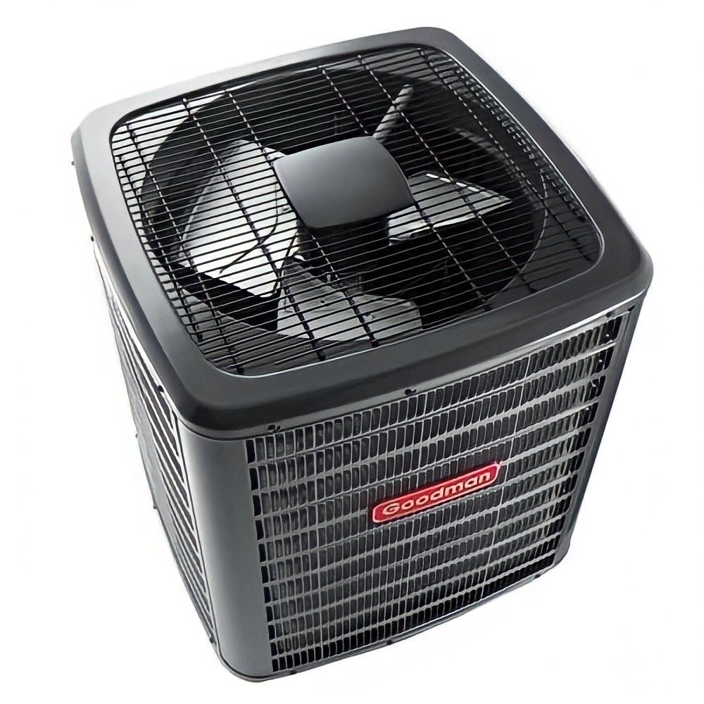
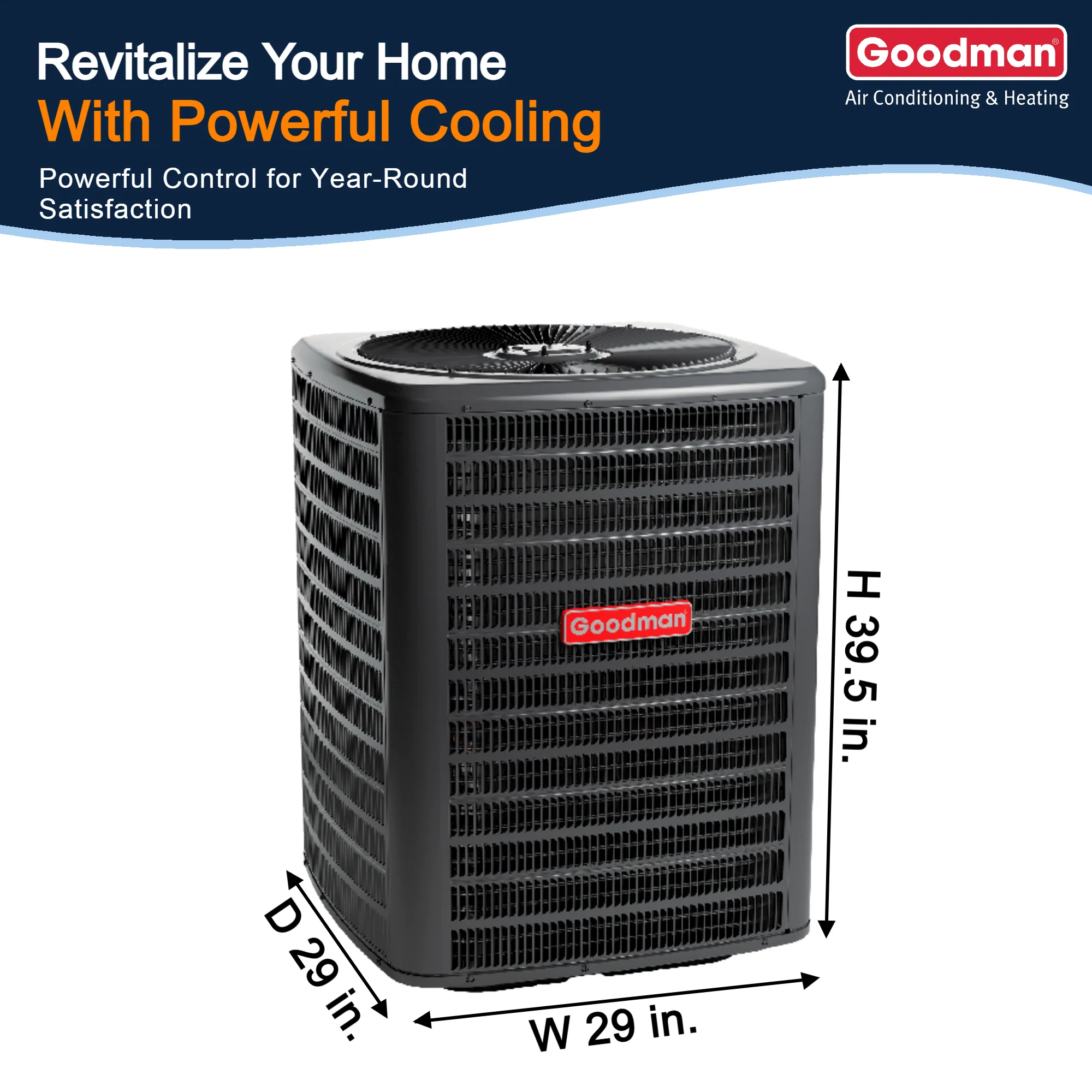
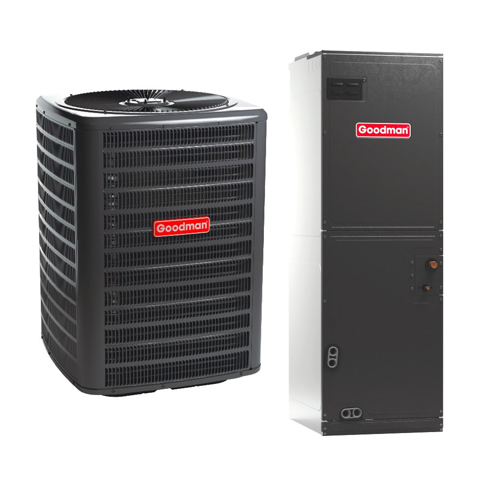
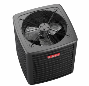
Today we’re using real-world logic, grounded in modern equipment like the Goodman 2.5 Ton 13.4 SEER2 R32 AC Condenser (Model GLXS3B3010) as our reference point.
Let’s build your understanding from the ground up.
🔧 1. The Four Pillars of HVAC System Design
Before you grasp the big picture, you need to understand the core components:
1. Equipment (condenser, coil, air handler/furnace)
This is the horsepower of the system: the compressor, blower, and heat exchange surfaces.
2. Refrigerant circuit (line sets, charge levels, metering device)
This determines how efficiently heat moves from indoor → outdoor.
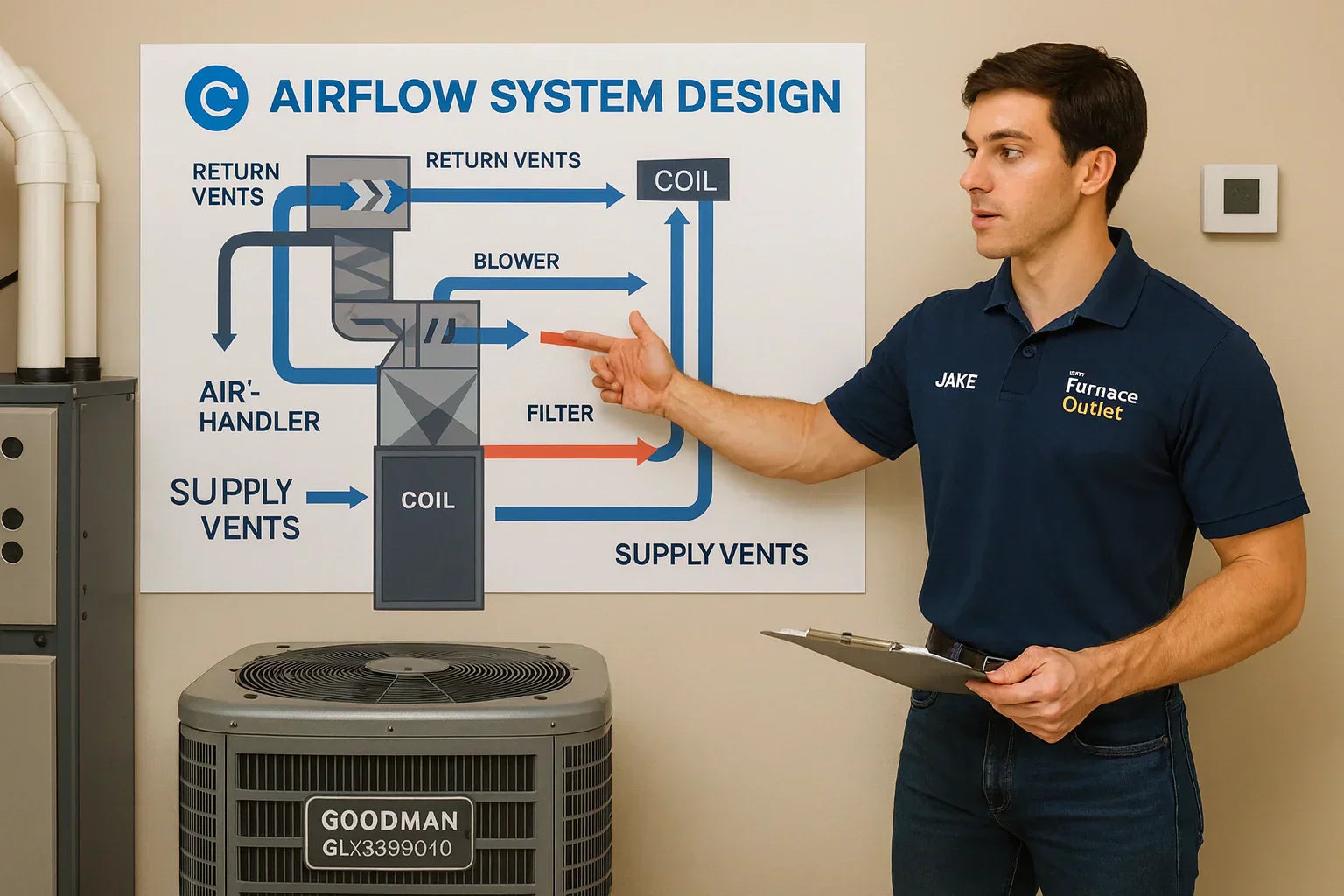
3. Airflow system (ductwork, returns, registers, filters)
This dictates how conditioned air travels throughout your home.
4. Controls (thermostat, sensors, staging, safety switches)
This tells the system when and how to run.
Every HVAC problem most homeowners experience—hot rooms, short cycling, weak airflow, humidity issues—traces back to one of these pillars.
Most installers only look at pillar #1.
Real system design means respecting all four.
🌬️ 2. The “Airflow First” Rule — The Foundation of System Design
Airflow determines capacity. Capacity determines comfort.
Get airflow wrong, and you can buy the fanciest R-32 condenser on the planet—it still won’t cool right.
Correct airflow for a 2.5-ton system:
📌 350–450 CFM per ton
So a 2.5-ton system requires:
➡️ 875–1,125 CFM of actual delivered airflow
Now here’s the problem:
Most homes only deliver 600–800 CFM due to:
-
undersized returns
-
flex duct restrictions
-
90° elbows everywhere
-
choked filters
-
poorly sealed plenums
-
high static pressure
-
sloppy transitions
If airflow drops…
Your evaporator coil runs cold → refrigerant can’t boil properly → humidity removal stops → the compressor overheats → the system short cycles → and the equipment dies early.
This is why system design starts with ducts, not tons.
📐 3. The Ductwork Blueprint — Why 90% of Homes Are Choked
Poor duct design is the #1 reason new systems underperform.
3 Core Rules of Duct Design
1. Returns must equal supplies
A 2.5-ton system typically needs:
-
1 large 18" return, OR
-
2 medium 14" returns
Most homes?
One small 12" return struggling to feed the entire system.
2. Flex duct cannot exceed 5% compression
If your duct looks like a snake that swallowed a bowling ball…
Your airflow is toast.
3. Friction rate must stay below 0.08" WC
Higher friction means higher static pressure—your blower works harder, fails faster, and delivers less air.
For deeper duct design standards, see:
👉 Air Duct Design System Guidelines (North Carolina State)
https://www.ncdoi.gov/media/1437/open
❄️ 4. How the Outdoor Condenser Fits Into the System Design
Let’s use the Goodman GLXS3B3010 R-32 2.5-Ton Condenser as an example.
A condenser’s job is simple:
**It removes heat from the home.
But only if the rest of the system is designed for it.**
Here’s what affects condenser performance:
1. Line-set length
Most R-32 systems require:
-
minimum 10 ft
-
maximum 50–75 ft (varies by manufacturer)
Longer runs = pressure loss = efficiency drop.
2. Vertical lift
Too much vertical rise (from basement to attic) increases refrigerant pressure imbalance.
3. Metering device match
TXV vs piston mismatches cause:
-
low suction pressure
-
coil freeze-ups
-
poor superheat
-
bad subcooling
-
compressor flooding
4. Clearance and airflow
A condenser needs:
-
24–36 inches clearance on all sides
-
5 feet above
-
zero obstructions on the fan discharge plane
Blocked airflow = hot refrigerant = poor cooling = compressor stress.
For verified outdoor clearance rules:
👉 ENERGY STAR HVAC Installation Guidelines
https://www.energystar.gov
⚙️ 5. The Refrigerant Circuit — Where Most Homeowners Get Lost
Think of refrigerant as the delivery driver carrying heat out of your home.
In a modern system, here’s what matters:
🧊 Evaporator Coil
Absorbs heat and humidity from indoor air.
Needs correct:
-
airflow
-
refrigerant charge
-
metering device
-
coil sizing (must match condenser)
A mismatched coil is the #1 cause of:
-
coil freeze
-
warm air from vents
-
short cycling
🔥 Compressor
Acts as the heart of the system.
Cannot survive:
-
low refrigerant
-
contaminated line sets
-
excessive superheat
-
poor airflow across the evaporator
⚠️ Refrigerant charge
Most units arrive factory-charged for a 15 ft line set.
Anything above that requires precise adjustments.
For proper charging procedures (superheat/subcooling):
👉 HVACR Refrigerant Charging Guide – ESCO Institute
https://www.escogroup.org
🔄 6. The Air Handler/Blower — The System’s Pressure Engine
Your blower isn’t just a fan.
It’s a pressure machine that must overcome friction in:
-
supply ducts
-
return ducts
-
coil
-
filter
-
grilles
-
transitions
The blower is designed for a maximum pressure known as total external static pressure (TESP).
Most systems are designed for:
➡️ 0.5 in. WC total
Yet most homes measure:
❌ 0.8–1.2 in. WC
When static pressure rises:
-
airflow drops
-
blower overheats
-
coil freezes
-
refrigerant pressures crash
-
compressor is starved
-
utility bills increase
-
lifetime decreases
For verified airflow/static standards:
👉 ACCA Manual D (Duct Design)
https://www.acca.org/standards/technical-manuals
🎛️ 7. The Thermostat & Controls — The Brain of the System
A thermostat does more than set temperature.
It controls:
-
blower speed
-
staging (single-stage vs two-stage)
-
humidity removal mode
-
fan delay
-
compressor protection
-
temperature swing logic
-
cycle time
Many comfort issues come from:
-
thermostats not set to “dehumidify mode”
-
blower speeds too high for humidity removal
-
temperature swings set incorrectly
-
no compressor delay (short cycling)
Smart thermostats like Ecobee help, but they must be programmed for your exact system design.
ENERGY STAR has guidance on thermostat optimization:
👉 https://www.energystar.gov/products/smart_thermostats
📊 8. System Design in Action: How All the Pieces Work Together
Here’s the full chain:
1. Thermostat calls for cooling
Control board activates:
-
compressor
-
condenser fan
-
evaporator blower
2. Air is pulled into returns
If returns are undersized → airflow bottleneck begins.
3. Air is filtered
Filter resistance adds to static pressure.
MERV 13 filters are great—but only with a large enough filter rack.
4. Air passes over evaporator coil
Heat + humidity → refrigerant absorbs it.
This requires:
-
correct airflow
-
correct charge
-
correct coil match
5. Refrigerant transports heat outdoors
Through the line set.
Too long, too kinked, too small = pressure problems.
6. Condenser rejects heat
Warm air expelled out the top.
Blocked airflow → system can’t cool → compressor overheats.
7. Refrigerant returns indoors cooled down
Cycle repeats until thermostat is satisfied.
A failure in any step breaks the whole chain.
🧱 9. The Hidden Components Most Homeowners Never See
1. Condensate drain & traps
Improper traps = water backups.
2. Safety float switches
Prevent ceiling floods.
3. Line-set insulation
Poor insulation = condensation → mold → water damage.
4. Duct mastic & sealing
Unsealed ducts can lose 20–40% of airflow.
5. Electrical disconnect
Required for safe servicing.
For safety and code details:
👉 National Electrical Code (NEC) HVAC Requirements
https://www.nfpa.org
📍 10. Where System Design Usually Fails (Jake’s Top 7 List)
1. Undersized returns
The #1 design flaw.
2. Ducts not designed for modern high-static EC blowers
Old systems ran at lower static.
New SEER2 systems require better ducts.
3. Incorrect airflow settings
Most blowers are factory-set too high or too low.
4. Coil mismatch
Especially when upgrading to R-32 equipment.
5. Poor condenser placement
Blocked airflow kills efficiency.
6. Line-set contamination
Installing new equipment on old line sets is a bad idea.
7. Thermostat programming errors
Wrong fan mode, staging, or temp swing = comfort issues.
🏗️ 11. The Jake Method: Designing a System the Right Way
Here’s how Jake explains design to homeowners:
Step 1 — Calculate Load (Manual J style)
You don’t need exact math, just:
-
square footage
-
insulation level
-
window count
-
climate zone
Step 2 — Check Existing Ductwork
Measure:
-
supply sizes
-
return sizes
-
static pressure
-
airflow
-
duct lengths
Step 3 — Match Equipment
Condenser, coil, air handler must be AHRI-matched.
Step 4 — Design the Line-Set Path
Short, smooth, insulated, no kinks.
Step 5 — Configure Controls
Thermostat must match your blower and system stage.
Step 6 — Verify Performance
Using:
-
CFM measurement
-
static pressure
-
superheat
-
subcooling
-
temperature split
This is how you know a system is actually performing.
⚡ 12. Want a Simple Summary? Here’s the Entire Blueprint in 30 Seconds
-
Airflow comes first.
-
Ductwork makes or breaks system performance.
-
The condenser only works right when matched to the coil & refrigerant charge.
-
The blower must overcome static pressure.
-
Thermostat settings must match your equipment.
-
Line sets must be clean, insulated, and properly sized.
-
Safety drain systems prevent catastrophic damage.
When all pieces work together, your home gets:
-
lower bills
-
consistent temperatures
-
better humidity control
-
quieter operation
-
longer equipment life
This is the blueprint pro installers follow—now you understand it too.
Buy this on Amazon at: https://amzn.to/47dm4yJ
In the next topic we will know more about: R-32 Isn’t Plug-and-Play: What Changes in Your System Design When You Upgrade to Modern Refrigerant

