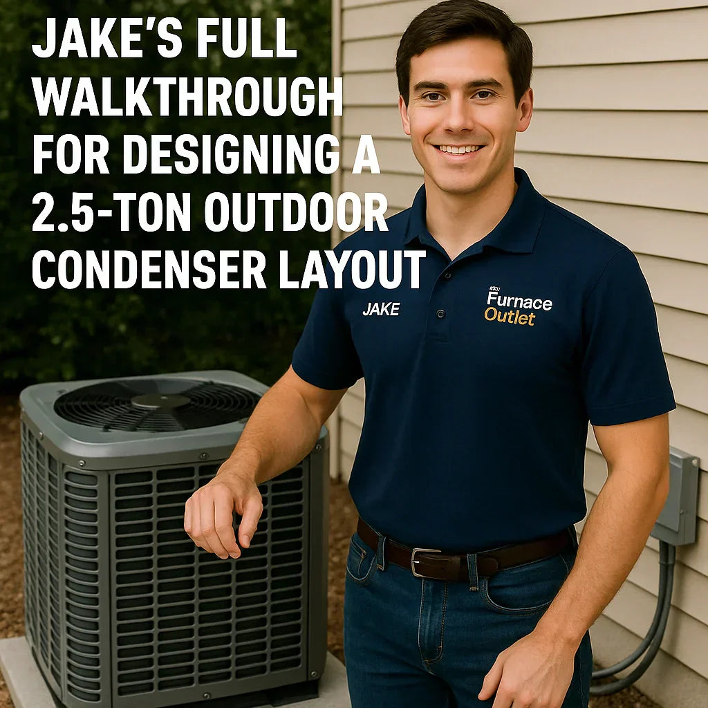
How to place, wire, protect, and future-proof your outdoor AC like a pro.
Designing the outdoor condenser layout for a modern 2.5-ton air conditioning system isn’t just about picking a spot outside and placing the unit on a concrete pad. If that were the case, every home would cool perfectly, installers wouldn’t get callback after callback, and homeowners wouldn’t wonder why their brand-new 2.5-ton system “still feels weak.”
Your outdoor condenser is the heart of the cooling system. Everything around it—from the pad height to the panel wiring to the refrigerant line path—affects:
-
System efficiency
-
Noise output
-
Lifespan
-
Refrigerant balance
-
Safety
-
Code compliance
-
Comfort
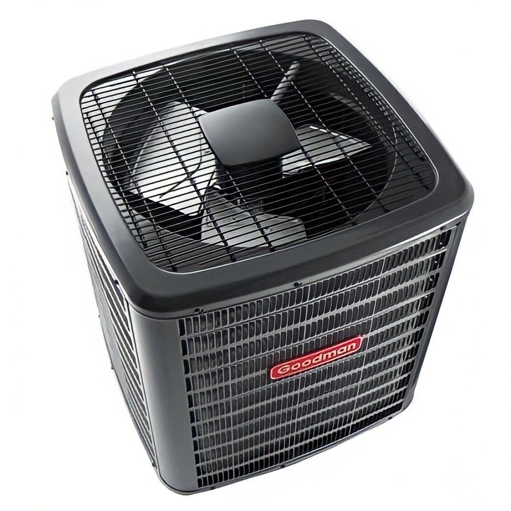
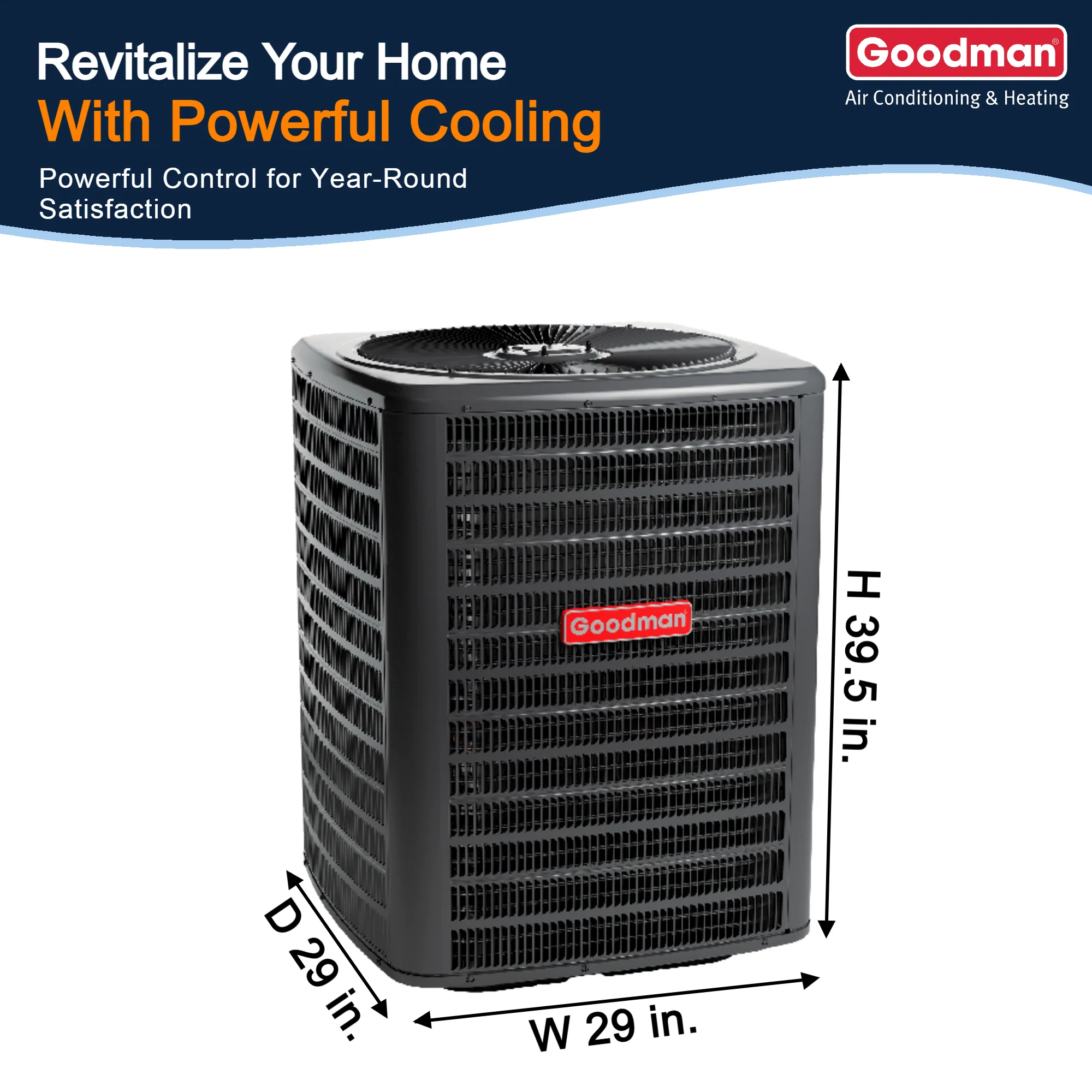
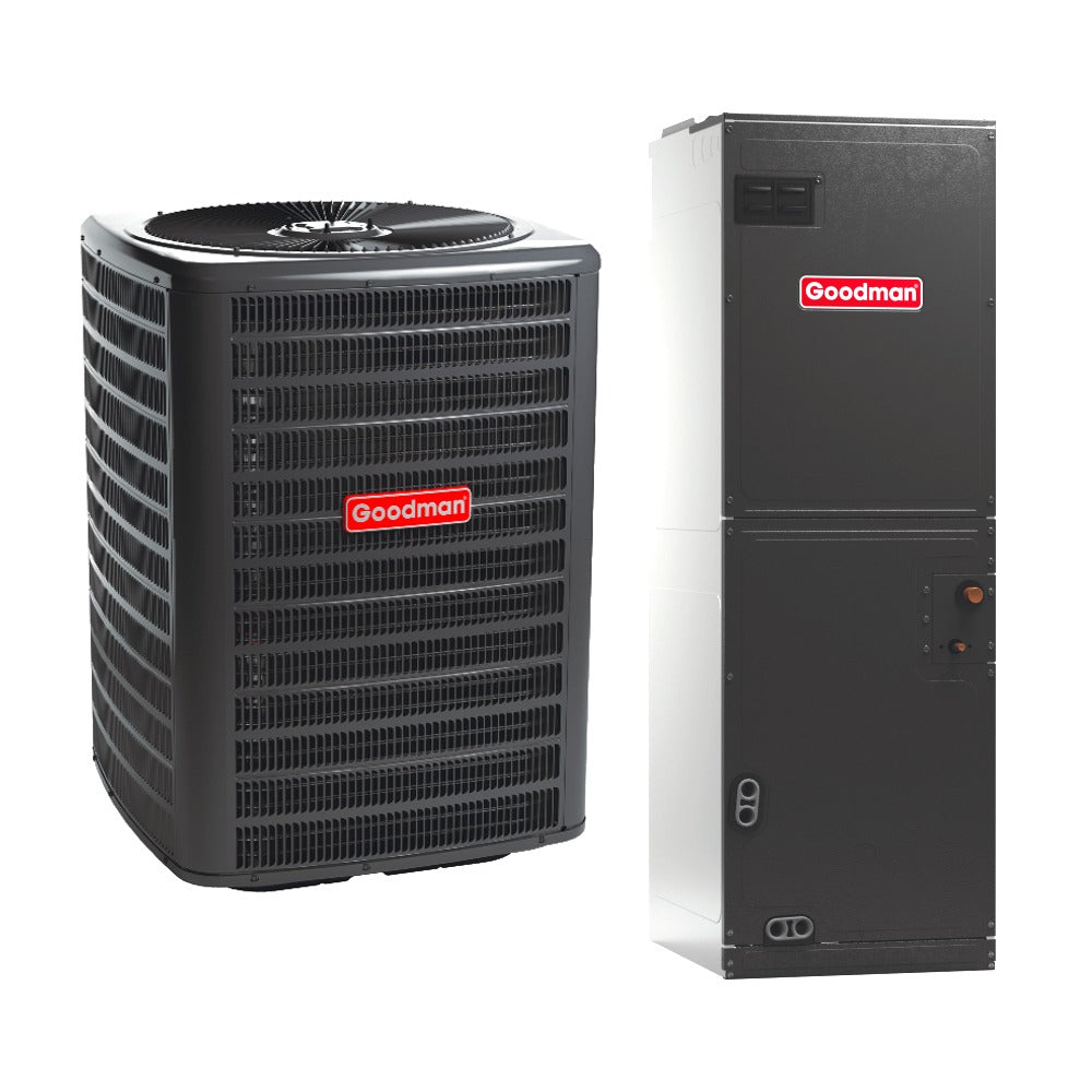
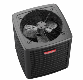
This is the complete Jake-approved guide to designing the perfect outdoor condenser layout for a 2.5-ton system—especially modern models like the Goodman GLXS series R-32 condensers.
Let’s build it step by step.
📏 1. Start With the Load: Why Your Layout Depends on Real Heat Removal Needs
Before we talk about pads, wiring, and clearances, there’s one thing homeowners overlook:
The condenser location directly affects system load.
Sun exposure, radiant heat, airflow around the outdoor coil, and even landscaping change how well a condenser can reject heat.
A system rated for SEER2 indoors will lose real-world efficiency outdoors if the condenser is placed poorly.
ASHRAE explains this thermal impact in their outdoor heat rejection standards:
ASHRAE Heat Rejection Principles
https://www.ashrae.org/technical-resources
Here’s the reality:
-
Condenser sitting in direct sunlight all day? Expect 2–7% less efficiency.
-
Placed in a narrow alley or fenced-in nook? Expect poor airflow + higher head pressure.
-
Too close to dryer vents or gas meters? Expect lint clogging and code violations.
So before placing anything on a pad, assess:
-
Sun path
-
Shade patterns
-
Wind direction
-
Proximity to outdoor living areas
-
Landscaping or obstructions
-
Snow/drainage paths
This info determines the best location for long-term performance.
🏡 2. Choosing the Proper Location: The “No-Compromise” Placement Rules
You’ve got flexibility—but only within the rules. A 2.5-ton condenser requires adequate air movement, service access, and safety clearance.
Here are Jake’s non-negotiables.
✔ Minimum Clearance Requirements
Most 2.5-ton condensers require:
-
24–36 inches of side clearance
-
60 inches above the fan discharge
-
At least 6 inches rear clearance to walls
-
Unrestricted airflow on the coil-intake sides
ENERGY STAR outlines these general outdoor unit placement standards:
ENERGY STAR AC Installation Guidelines
https://www.energystar.gov
Jake’s rule of thumb:
“If the condenser can’t breathe, your house can’t cool.”
✔ Avoid These Problem Areas
1. Narrow alleyways
Too restrictive for return airflow.
2. Direct exhaust locations
Avoid placing the condenser near:
-
Dryer vents
-
Furnace exhaust
-
Gas meters
-
Bathroom exhausts
Lint and acidic exhaust gases corrode coils quickly.
3. Deck overhangs and porch coverings
Any air recirculation kills performance.
4. Mulch beds
Mulch promotes moisture and coil corrosion; gravel is safer.
✔ Ideal Placement Scenarios
Best: North or East Side of Home
Stays coolest and avoids afternoon sun.
Good: Shaded South Side
As long as airflow is unrestricted.
Acceptable: West Side With Shade Structure
Only if properly ventilated.
🧱 3. The Pad: Height, Material, Leveling & Long-Term Stability
A condenser is only as solid as the pad it sits on. A tilted or sinking pad causes:
-
Compressor damage
-
Oil migration issues
-
Refrigerant imbalance
-
Vibration and noise
-
Early system failure
Here’s how to design the perfect pad setup.
✔ Pad Material Options
1. Pre-formed Composite Pad (Recommended)
Lightweight, durable, non-absorbing.
2. Concrete Pad
Long-lasting but heavy and can crack if soil shifts.
3. Wall-mounted Bracket (Only When Required)
Used for tight lots or high snow zones—but increases vibration.
✔ Pad Height
Jake’s rule:
“Pad should be at least 2–3 inches above grade, or 6 inches in flood-prone areas.”
This prevents:
-
Snow blockage
-
Grass ingestion
-
Water intrusion
-
Ice buildup against the coil
FEMA offers useful flood elevation guidelines for outdoor mechanical equipment:
FEMA Mechanical Elevation Standards
https://www.fema.gov
✔ Leveling the Pad
A condenser must be perfectly level. Even a 1/4-inch tilt can misalign the compressor and cause long-term oil pooling.
Best practice:
-
Use crushed gravel base
-
Compact the soil
-
Add drainage slope away from the home
This ensures long-term stability even in freeze-thaw climates.
🌬️ 4. Designing the Airflow Envelope: How to Keep the Condenser Breathing
The outdoor coil needs unobstructed 360° airflow. Any blockages cause:
-
High head pressure
-
Poor heat rejection
-
Compressor overload
-
Short cycling
-
Reduced SEER2 efficiency
Jake calls this the “airflow envelope”—the invisible bubble around the condenser that must remain clear.
✔ Vegetation Rules
-
No bushes within 3 feet
-
No overhanging trees shedding debris
-
Avoid grass clippings entering the coil
Landscaping rules from Green Building Advisor support this approach:
GBA Outdoor HVAC Airflow Guide
https://www.greenbuildingadvisor.com
✔ Fence / Screen Requirements
If fencing or screening is used:
-
Must be louvered
-
Must allow minimum 50% free airflow
-
Must maintain 24–36 inch clearance from unit
Decorative screens that look nice but choke airflow?
A disaster waiting to happen.
✔ Snow & Ice Considerations (Northern Homes)
For cold climates:
-
Elevate pad 6–12 inches
-
Ensure snow does not drift into discharge path
-
Avoid rooflines that dump snow on condenser
Heat pumps especially depend on this.
📐 5. The Line-Set Route: Length, Bend Radius, Lift & A2L Requirements
With modern refrigerants like R-32, line-set design is more critical than ever.
Why?
Because R-32 systems:
-
Use lower charge amounts
-
Are more sensitive to pressure drop
-
Have higher discharge temperature
-
Follow A2L safety classification rules
Let’s design the line-set properly.
✔ Line-Set Length Requirements
Most manufacturers specify:
-
Minimum: 10 ft
-
Maximum: 50–75 ft
-
Maximum elevation difference: 20–30 ft
Longer runs require:
-
Charge adjustments
-
Suction line sizing changes
-
Additional oil traps (in some systems)
Incorrect lengths = poor capacity.
✔ Bend Radius & Slope Rules
-
No compressed or kinked bends
-
Maintain minimum bend radius (typically 4–6 inches)
-
Suction line slopes back toward compressor
-
Avoid rigid 90° angles
Kinked lines destroy compressor reliability.
✔ A2L (R-32) Refrigerant Routing Rules
Per UL 60335-2-40, refrigerant piping must avoid:
-
Ignition sources
-
Unventilated cavities
-
Sharp edges
-
Areas with high occupant exposure
Reference:
UL A2L Refrigerant Piping Requirements
https://www.ul.com
✔ Insulation Requirements
R-32 systems require:
-
Continuous insulation
-
Closed-cell foam
-
UV-resistant external covering
Gaps or tears lead to condensation, mold, and efficiency loss.
⚡ 6. Electrical Layout: Breakers, Disconnects, Whips & Bonding
Designing the electrical layout is where many DIYers get stuck. A 2.5-ton condenser typically requires:
-
A 20A–30A dedicated breaker
-
A properly sized disconnect
-
Correct wire gauge (usually 10/2 or 8/2)
-
A whip (flex conduit)
-
Proper ground bonding
NFPA code outlines these electrical requirements:
NEC Outdoor HVAC Electrical Standards
https://www.nfpa.org
Let’s break down each component.
✔ 1. The Breaker
Must match:
-
Manufacturer MCA (Minimum Circuit Ampacity)
-
MOP (Maximum Overcurrent Protection)
Never oversize a breaker; it’s both unsafe and code-violating.
✔ 2. The Disconnect Box
Installed within sight of the unit, typically:
-
Fusible or non-fusible
-
Mounted at 4–6 feet height
-
Positioned 1–4 feet from condenser
Disconnects protect service techs from live circuits.
✔ 3. The Electrical Whip
Flexible conduit connecting disconnect → condenser.
Whip must be:
-
UV-rated
-
Liquid-tight
-
Proper gauge
✔ 4. Grounding & Bonding
Outdoor units must be properly grounded using:
-
Ground lug
-
Bare copper or green wire
-
NEC-compliant bonding
Missing grounding = fire hazard.
📡 7. Noise Control: Designing a Quiet Outdoor Space
A poorly placed condenser is loud and disruptive.
A properly designed one is barely noticeable.
Here’s how to make it quiet.
✔ Sound-Dampening Placements
Best: Against the house exterior wall, not floating in an open yard.
The wall reflects noise away from patios and bedrooms.
✔ Anti-Vibration Pads
Place vibration pads between:
-
Condenser feet
-
Pad surface
This reduces startup rumble and harmonic vibration.
✔ Avoid Corner Amplification
Corners create acoustic “megaphones.”
Never place the condenser between:
-
Two walls
-
A wall and a fence
-
A wall and a deck post
Noise doubles in these configurations.
✔ Add Soft Landscaping for Absorption
Gravel, shrubs (at safe distance), and mulch reduce reflected noise.
🧪 8. Commissioning: Setting Up the System After Installation
The layout is only perfect if the commissioning process is perfect too.
Jake’s commissioning checklist includes:
✔ Superheat & Subcooling Verification
Even R-32 systems using factory TXVs must be charged precisely.
Incorrect levels = poor cooling.
✔ Electrical Testing
-
Voltage drop
-
Amp draw
-
Compressor startup characteristics
-
Fan motor amperage
✔ Airflow Testing Inside
Outdoor performance depends on indoor airflow.
Static pressure should be:
-
0.3–0.5 in WC total
Anything above 0.8 in WC = airflow crisis.
✔ Condenser Performance Monitoring
Check:
-
Head pressure
-
Suction pressure
-
Coil temperature differential
-
Fan RPM
🧭 9. Long-Term Maintenance Design: Planning for Serviceability
The outdoor layout must allow easy access for:
-
Coil cleaning
-
Electrical inspection
-
Refrigerant service
-
Fan motor replacement
-
Defrost board access
-
Contactor/capacitor swaps
Jake recommends 18–24 inches of service clearance on at least two sides.
Avoid landscaping that blocks maintenance.
💡 10. Jake’s Final Outdoor Layout Formula
Here’s the condensed, homeowner-friendly version:
1. Choose a shaded area with 24–36 inches of clearance.
North or east side preferred.
2. Install a composite pad 2–3 inches above grade.
Level it on crushed gravel.
3. Route line sets cleanly with no kinks and proper insulation.
Maintain manufacturer length rules.
4. Run electrical with correct breaker, disconnect, whip, and grounding.
Follow NEC and manufacturer MCA/MOP.
5. Ensure noise-friendly placement.
Avoid corners and reflective surfaces.
6. Provide full service clearance.
At least 18–24 inches on both coil-access sides.
7. Verify refrigerant charge and airflow during commissioning.
Critical for SEER2 performance.
🔚 Final Thoughts from Jake
Designing a 2.5-ton outdoor condenser layout isn’t just following installation steps. It’s understanding the physics, airflow, electrical safety, refrigerant behavior, and home environment that shape system performance.
For most homeowners, a perfectly designed outdoor condenser layout will:
-
Lower energy bills
-
Improve cooling capacity
-
Extend system lifespan
-
Reduce noise
-
Prevent breakdowns
-
Maintain manufacturer warranty
Get the layout wrong, and even the best 2.5-ton system feels weak.
Get it right, and the comfort difference is obvious the moment it turns on.
Buy this on Amazon at: https://amzn.to/47dm4yJ
In the next topic we will know more about: Airflow First, Equipment Second: The Design Rule 90% of DIYers Ignore

