Jake’s complete guide to the part of your HVAC system most homeowners never think about—but that determines whether your system runs flawlessly or fails early.
Most homeowners—and even many DIY installers—think the refrigerant line set is simple:
“It’s just two copper pipes that connect the condenser outside to the coil inside.”
But the reality is:
The line-set path is one of the most critical design factors in ANY HVAC installation—especially modern R-32 systems.
A poorly designed line set can reduce system capacity, destroy compressor performance, create oil return issues, and even void manufacturer warranties.
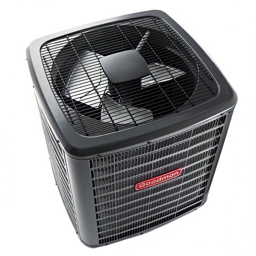
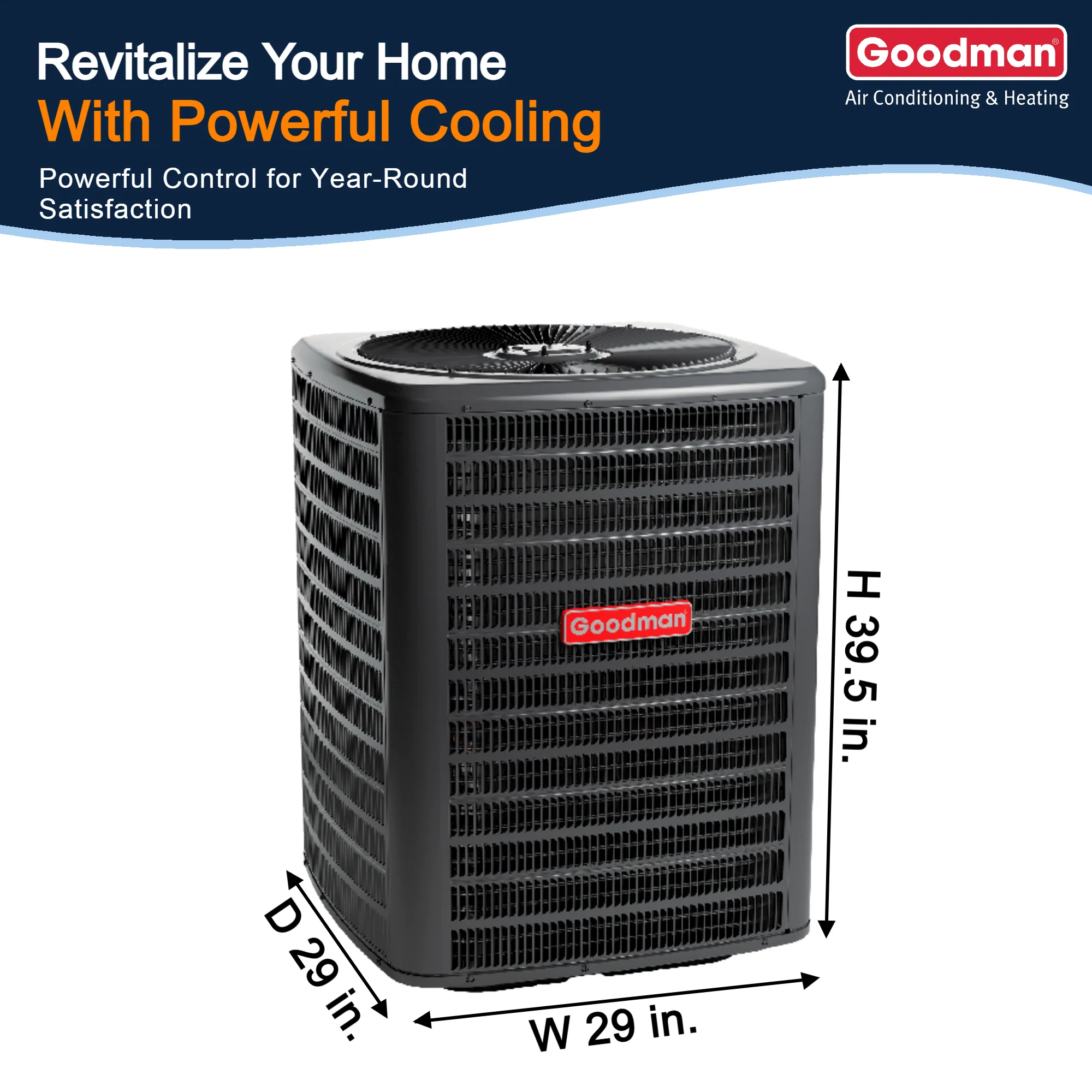
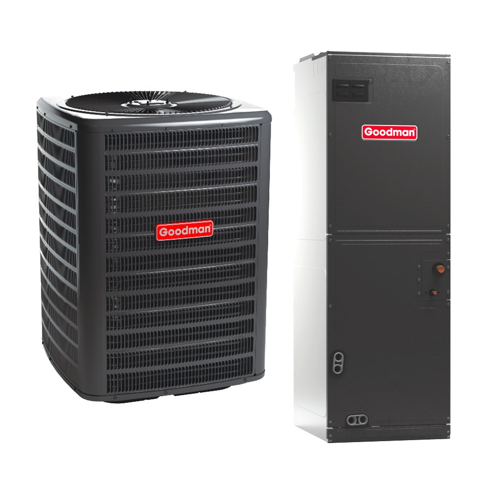
2.5 Ton Up To 15 SEER2 Goodman Air Conditioner Model - GLXS3BN3010
Meanwhile, a properly designed line set:
-
Increases system efficiency
-
Stabilizes refrigerant pressures
-
Extends compressor life
-
Reduces noise
-
Improves cooling performance
-
Helps maintain SEER2 ratings
Today, Jake walks you through EVERYTHING that goes into designing the perfect line-set path—no kinks, no overheating, no airflow restrictions, no hidden traps.
Let’s build your line-set blueprint step by step.
🔧 1. What the Line Set Actually Does (Jake’s Clear Explanation)
Your air conditioner works by moving heat—not air—from inside the home to outdoors. The line set is the highway that transports refrigerant between:
-
The outdoor condenser (heat rejection)
-
The indoor evaporator coil (heat absorption)
The line set consists of:
1. Suction Line (larger insulated pipe)
Carries cool refrigerant vapor back to the compressor.
2. Liquid Line (smaller copper pipe)
Carries high-pressure liquid refrigerant into the evaporator coil.
ASHRAE outlines these functions clearly in their residential refrigeration basics: ASHRAE Refrigeration Principles Overview
If these two lines are not perfectly designed, the refrigerant cycle becomes unstable, and the system loses efficiency—even if the equipment is brand new.
🌡️ 2. Why Modern R-32 Systems Are More Sensitive to Line-Set Design
R-22 allowed sloppy design.
R-410A tolerated some mistakes.
R-32 tolerates almost none.
Here’s why:
1. R-32 uses lower refrigerant mass
Meaning small pressure drops affect system performance dramatically.
2. R-32 runs hotter on the discharge side
Poor line routing causes refrigerant to overheat.
3. R-32 is an A2L refrigerant
Requires safer routing and fewer possible leak points.
4. R-32 coils and TXVs are tuned to precise pressure targets
Any turbulence or restrictions disrupt the balance.
5. R-32 manufacturers specify tighter limits
Length, rise, and bend requirements matter more than ever.
Daikin’s R-32 engineering documents highlight this sensitivity: Daikin R-32 Refrigerant Engineering Guide
So yes—your line-set path will make or break the performance of a modern R-32 2.5-ton system.
🗺️ 3. Step One: Plan the Shortest, Straightest Line-Set Route
Every foot of copper pipe adds:
-
friction loss
-
pressure drop
-
heat gain
-
potential oil trapping
-
installation cost
Manufacturers typically specify a:
-
minimum length: 10 ft
-
maximum length: 50–75 ft
-
maximum vertical lift: 20–30 ft
Every 10 ft over the “factory charge” distance will require additional refrigerant—something the EPA warns must be handled with precision:
EPA Refrigerant Handling Regulations
https://www.epa.gov/section608
Jake’s Golden Rule #1:
Keep the line-set path as short and straight as humanly possible.
No zigzags.
No unnecessary turns.
No “creative” routing.
➿ 4. Avoiding Kinks: The #1 Line-Set Killer
A kink in the suction or liquid line is catastrophic.
Here’s what happens:
❌ Velocity drops
❌ Superheat changes
❌ Oil return stops
❌ Compressor overheats
❌ System loses capacity
Typical kink-causing mistakes include:
-
Bending pipe without a proper bending tool
-
Running line sets through tight holes
-
Trying to make sharp 90° turns
-
Pulling soft copper too hard during installation
-
Compressing bends inside the wall
If you must bend copper:
✔ Use a ¾" or 1” radius bending tool
✔ Keep bends smooth and gradual
✔ Never twist the pipe
✔ Never compress flex lines by hand
Green Building Advisor explains why kinked refrigerant lines destroy capacity:
GBA Refrigerant Line-Set Best Practices
https://www.greenbuildingadvisor.com
⚠️ 5. Why You Should Minimize—or Completely Avoid—Joints and Fittings
Every joint is:
-
A restriction
-
A turbulence point
-
A potential leak
-
A future service problem
R-32 refrigerant requires A2L-safe fittings, which are built to tighter tolerances. Still:
More joints = more problems.
This is why manufacturers recommend continuous, unbroken line sets.
If a joint is unavoidable:
-
Use properly torqued, approved flare fittings
-
Never solder (soft solder fails under pressure)
-
Braze only with nitrogen flowing (mandatory)
UL provides essential safety guidelines for A2L (R-32) refrigerant piping:
UL 60335-2-40 A2L Safety Requirements
https://www.ul.com
🔥 6. Keep Line Sets Away From Heat Sources (One of Jake’s Biggest Rules)
Heat affects refrigerant in the liquid line, causing:
-
flashing
-
vapor bubbles
-
incorrect TXV operation
-
loss of cooling capacity
Never run line sets next to:
❌ Water heaters
❌ Furnaces
❌ Steam pipes
❌ Dryer ducts
❌ Attic radiant barriers
❌ Metal roofs without insulation
Ideal placement should be:
-
shaded
-
insulated
-
thermally stable
This ensures the liquid line stays genuinely liquid, not a bubbly mixture that starves the evaporator coil.
🧊 7. Proper Insulation: Prevent Condensation, Heat Gain & Efficiency Loss
For R-32 systems:
Only use closed-cell insulation with UV protection.
The suction line must be fully insulated because it carries cold refrigerant vapor back to the compressor.
If the insulation is:
-
torn
-
compressed
-
missing
-
water-soaked
-
UV-damaged
…you get:
-
condensation
-
mold
-
higher static pressure in ducts
-
lower compressor efficiency
-
refrigerant migration
The EPA notes that poor insulation significantly reduces efficiency:
EPA Residential Energy Efficiency Guidelines
https://www.epa.gov/energy
Jake’s rule:
✔ Minimum ½" insulation thickness
✔ ¾"–1" in hot climates
✔ UV-rated insulation for outdoor sections
✔ No gaps, no tears, no compression
📏 8. Vertical Rise: The Hidden Factor That Destroys Oil Return
Vertical rise is the difference in height between the indoor coil and outdoor condenser.
Too much rise causes:
-
oil to pool in low points
-
compressor lubrication issues
-
higher head pressure
-
noisy operation
-
premature compressor failure
Manufacturers typically allow:
20–30 ft of maximum vertical rise
Beyond that, oil traps may be required.
An oil trap is a small U-shaped copper section designed to pull oil uphill with high-velocity vapor.
✔ Install oil traps every 20 ft of vertical rise
✔ Never put traps on the liquid line
✔ Avoid unnecessary elevation changes
🏠 9. Line-Set Routing Through Walls: Do NOT Let It Float
If your line set runs inside a wall cavity, it must:
-
be strapped
-
be isolated from studs
-
be protected with grommets
-
not rub or vibrate
Copper contacting wood or metal creates:
-
noise
-
line wear
-
refrigerant leaks
NEC guidelines show how mechanical pipes must be protected inside framing:
NFPA / NEC Mechanical Penetration Requirements
https://www.nfpa.org
Jake’s method:
✔ Use rubber isolators
✔ Strap every 4 ft
✔ Avoid tight holes
✔ Protect against vibration
⚙️ 10. Condensate & Line-Set Coordination
Your line set should never block:
-
the secondary drain pan
-
the primary drain
-
the float switch path
-
service access to the coil
The line-set route must allow:
-
coil removal
-
block removal
-
drain clearing
Jake always leaves 12–18 inches of straight copper at the air handler.
🔌 11. Electrical + Line-Set Separation Requirements
Never strap refrigerant lines to:
-
high-voltage wiring
-
conduits
-
thermostat cable
-
communication lines
Electrical heat = refrigerant heat gain.
And vibration = electrical wear.
Always keep:
✔ 3–6 inches between electrical and refrigerant lines
✔ Separate strapping points
✔ Different penetration holes
⚡ 12. Wall Sleeves, Line-Set Covers & UV Protection
All outdoor runs should be inside:
-
line-set covers
-
wall sleeves
-
UV-rated insulation
Benefits:
-
cleaner installation
-
rodent protection
-
UV protection
-
weatherproofing
-
easier future servicing
Line-set covers also prevent:
-
hail damage
-
weed-eater destruction
-
physical kinks
🔍 13. Testing the Perfect Line-Set Path: Jake’s Commissioning Steps
Once installed, Jake performs:
1. Pressure Test (300–450 PSI nitrogen)
Checks for leaks.
2. Standing Pressure Test (24 hours if needed)
Ensures no micro leaks.
3. Deep Vacuum (≤ 500 microns)
Removes moisture, which reacts with POE oil.
4. Micron Rise Test (10 minutes)
Ensures lines are dry and sealed.
5. Charge Verification (SH/SC or factory charts)
Charge must match both line length and condenser specs.
6. System Monitoring (15–20 minutes)
Checks:
-
suction pressure
-
head pressure
-
superheat
-
subcooling
-
coil temperature
-
compressor amps
If the line-set path is wrong?
These numbers instantly show it.
🏁 14. Jake’s Final Rules for Designing the Perfect Line-Set Path
This is the punch list Jake uses on every job:
✔ Shortest path possible
✔ Least bends possible
✔ No kinks, ever
✔ No soft 90° bends under strain
✔ Avoid heat sources
✔ No unnecessary joints
✔ Proper insulation everywhere
✔ Respect vertical rise limits
✔ Use traps if needed
✔ Protect the lines inside walls
✔ Cover outdoor runs
✔ Pressure test + deep vacuum
Follow these—and your R-32 system will run at peak performance for decades.
Ignore them—and you’ll be paying for repairs on a brand-new system.
🔚 Final Thoughts from Jake
The line set is not an afterthought.
It is not a simple copper connection.
It is not something to “just run through the house wherever it fits.”
A perfectly designed line-set path:
-
Makes your system quieter
-
Protects your compressor
-
Stabilizes system pressure
-
Improves comfort
-
Preserves SEER2 efficiency
-
Avoids expensive leaks
-
Extends system life
In HVAC design, the line-set path is one of the highest-impact, lowest-visibility parts of the entire installation.
Get it right—and your system will always perform.
Get it wrong—and nothing else will work correctly.
Buy this on Amazon at: https://amzn.to/47dm4yJ
In the next topic we will know more about: The Quiet System: Jake’s Acoustic Design Tricks for a Low-Noise AC Install