What DIY Load Calculators Actually Do and Why Manual J Matters
Manual J–based calculators translate your home’s envelope, occupancy, and climate into sensible (temperature) and latent (moisture) loads. Quality tools (including cloud options modeled on Manual J) accept room-level inputs, orientation, building materials, and local weather data to generate BTU/hr targets you can design around. Avoid square-foot “shortcuts”; they routinely oversize, driving short cycling, poor humidity control, and higher bills.
Visual:
Inputs ──► Envelope + Occupancy + Weather ──► Sensible & Latent Loads ──► Equipment & Ducts
Cross-check calculator weather stations with your actual location. A 5–10% error in design temperature can swing tonnage.
Field-Grade Data Collection: The Measurement Checklist
Start with a sketch. For each room, record length × width × ceiling height, wall construction, insulation levels (attic, walls, floor), window/door type, orientation, and shading. Add occupancy and internal gains (cooking, electronics). Note duct location (conditioned vs. attic/garage).
Mini checklist:
-
Envelope: R-values, air leakage notes (recessed cans, chimney chases).
-
Fenestration: U-factor, SHGC, frame type, low-E coatings.
-
Orientation: true azimuth or compass corrected for magnetic declination.
-
Infiltration: visual cues (attic hatch gap, weatherstripping).
Ceiling height materially affects volume; a 10-ft great room can add ~25% more load than an 8-ft room of the same footprint.For reference while you measure, keep our Sizing Guide open and bookmark the Design Center if you want a second set of eyes.
Climate and Envelope: Getting Design Conditions Right
Pick design temperatures close to local 0.4% (cooling) and 99% (heating) values; good calculators embed this. If you must approximate, use regional norms and sanity-check with nearby stations. Pair that with envelope quality: tight, well-insulated homes carry lower infiltration and conduction loads; leaky, poorly insulated homes do the opposite.
Visual glazing impact (typical ranges):
|
Window Type |
U-Factor |
SHGC |
Load Impact |
|
Double-pane clear |
0.48 |
0.70 |
High solar gain |
|
Low-E double-pane |
0.30 |
0.25–0.40 |
Balanced |
|
Triple-pane low-E |
0.20 |
0.20–0.30 |
Lower gain/loss |
South/west glazing and dark roofs in sunny climates push sensible gains; coastal/humid zones elevate latent load. Confirm shading from overhangs/trees at peak sun.
Exploring heat pump options? Cross-check your climate results against R32 heat pumps and dual-fuel packaged units.
Room-by-Room vs. Whole-House: Why Granularity Wins
Whole-house loads get you in the ballpark; room-by-room loads get you the seats you want. Room loads drive CFM, register sizing, and duct balancing. Calculators that itemize per-room results reduce hot/cold spots and let you choose zoning or multi-head ductless strategically.
Use cases:
-
Large, west-facing bonus room? Expect higher sensible load plan extra CFM or its own ductless head.
-
Tight bedrooms with minimal glazing? Lower CFM and quieter operation.
A 400–450 CFM/ton assumption is typical for cooling airflow, but high-latent climates may target ~350 CFM/ton to enhance dehumidification with your equipment tables.
Sensible vs. Latent: The Humidity Side of the Math
Sensible load addresses dry-bulb temperature. Latent load accounts for moisture from infiltration, showers, cooking, and people. In humid regions, misjudging latent load leads to cool but clammy rooms. Manual J–based calculators split these correctly when you provide occupancy, ventilation rates, and infiltration estimates.
Verify that your selected equipment’s SHR (Sensible Heat Ratio) aligns with the calculator’s split. If your latent load is high, choose coils/air handlers and blower setups that support lower CFM/ton and longer runtimes.
Visual—rule of thumb to avoid:
“1 ton per 500 sq ft” ✘
“Add a half-ton for upstairs” ✘
To target latent control with precision, consider variable-speed air handlers paired with inverter mini-splits.
Common Input Mistakes that Skew Loads
-
Ceiling height omitted: Use volume for great rooms, not just floor area.
-
Window data guessed: Pull labels for U/SHGC; if unknown, select conservative defaults.
-
Orientation off by 45°: Recheck azimuth solar gains are directional.
-
Infiltration underestimated: Older homes with vented attics usually rate “average” or “loose.”
-
Ducts in attic ignored: Add duct gains/losses if ducts are outside conditioned space.
A leaky supply system in a vented attic can add >10% to cooling load and depressurize the house, increasing infiltration.
From Load to Equipment: Matching Capacity, Airflow & Efficiency
Match the net total load (sensible + latent) to equipment at design conditions, not just nameplate tonnage. Consult expanded performance tables: capacity varies with outdoor temp, indoor coil, airflow, and line length. Ensure the blower can deliver target CFM at your expected external static pressure (ESP).
For cooling, aim for equipment 90–110% of design load at the design point. For heat pumps, verify low-ambient capacity or plan supplemental heat.
When DIY Isn’t Enough: Call for a Professional Manual J
Hire a pro when:
-
Complex geometry/multi-story homes complicate solar and stack effects.
-
New construction/major remodels require stamped Manual J for permits.
-
Tight latent specs (wine rooms, high-humidity markets, IAQ goals) demand precise moisture modeling.
-
Rebate/code programs mandate third-party documentation.
-
Conflicting calculator outputs or any uncertainty persists.
Pros use on-site inspections, blower doors (when applicable), and advanced software to tune inputs. If you need signed reports for AHJ or incentives, start with our Design Center or reach out via Contact Us.
Turning Loads into a Complete System Plan
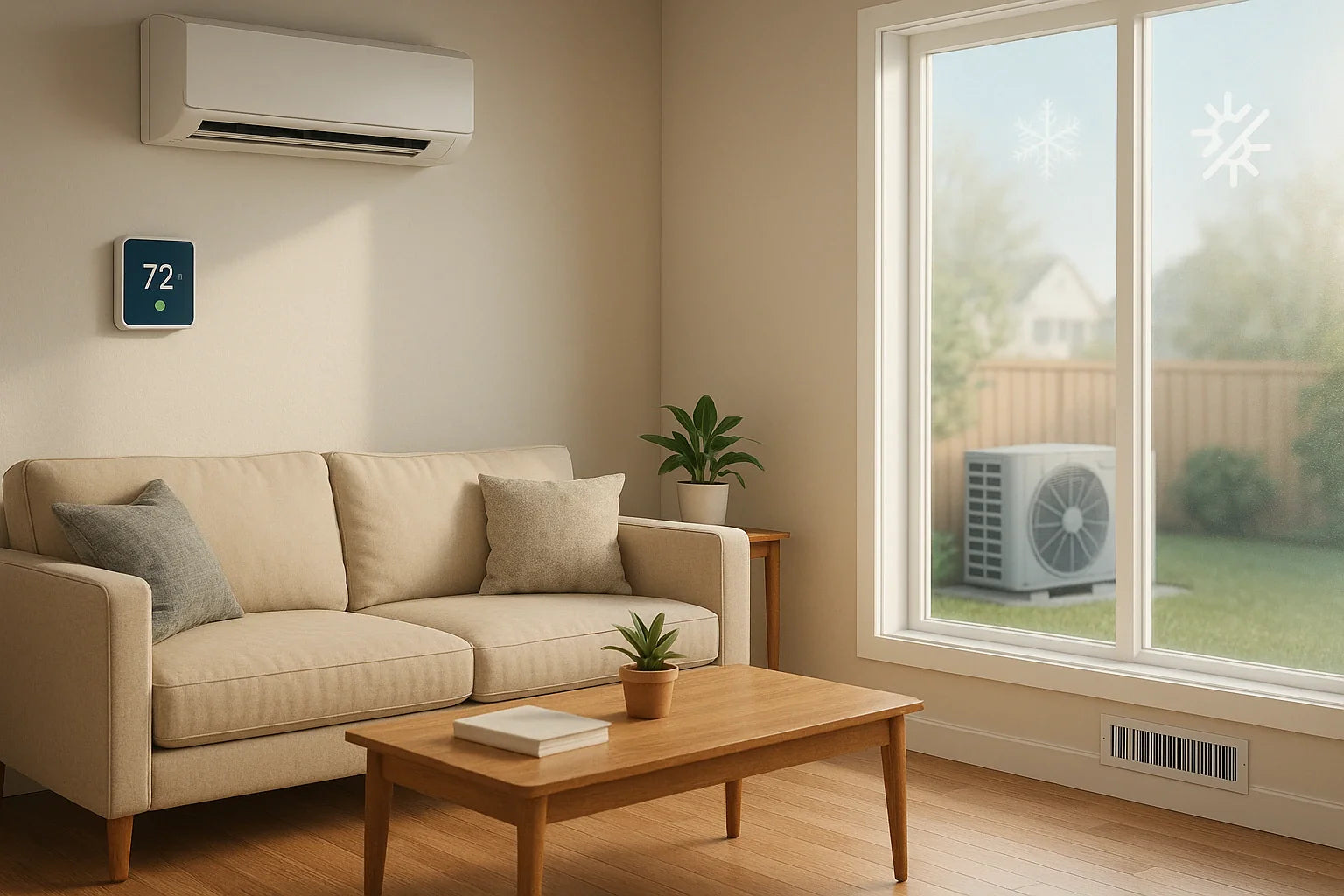
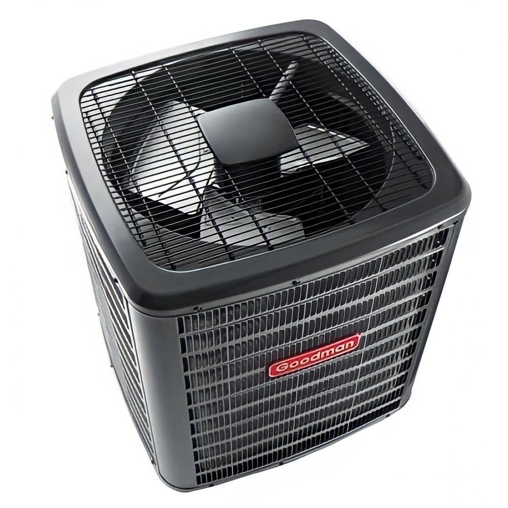
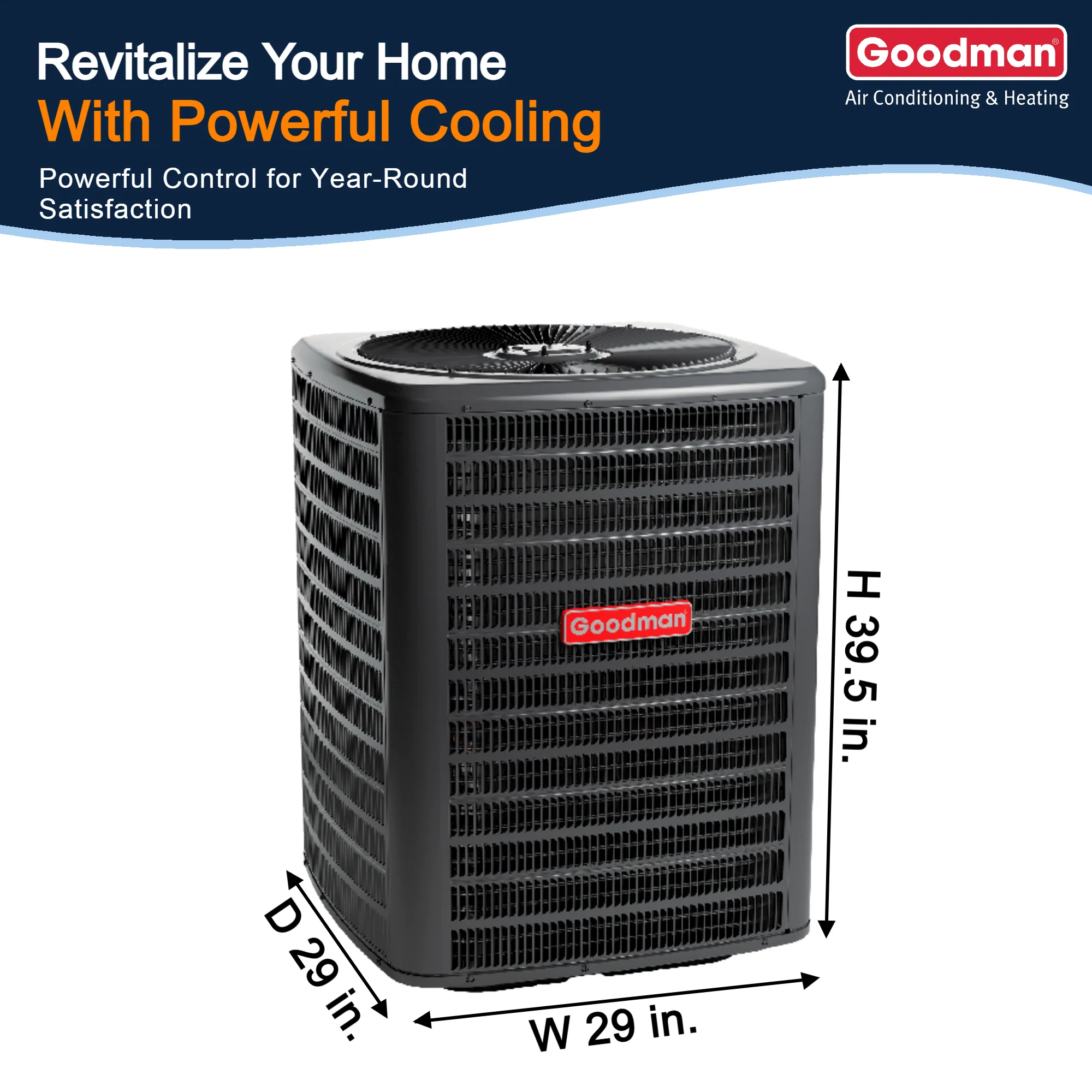
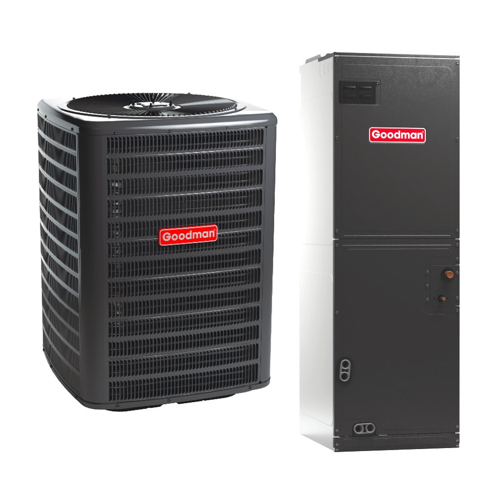
Loads inform system type, distribution, and controls. Small, scattered loads favor multi-zone ductless. Whole-house loads with existing ducts lean toward split systems or packaged units. In cold climates, consider dual-fuel or cold-climate heat pumps.
Size ducts for calculated room CFM and total ESP. Undersized returns are a top cause of noise and poor coil performance.
Visual—duct sizing context:
Room CFM ─► Branch size
Total CFM ─► Trunk size
ESP Limit ─► Blower selection
Finish with controls that support staging or inverter modulation for comfort and humidity.
A Repeatable DIY Workflow + Tooling Recommendations
-
Measure thoroughly (Section 2), then select a Manual J–based calculator. Many reputable diy-load-calculator-tools provide room-level inputs, climate lookup, and editable reports.
-
Enter conservative but realistic envelope and infiltration values.
-
Generate room and whole-house loads; iterate if any inputs feel “off.”
-
Translate loads to equipment at design conditions; verify airflow and ESP.
-
Choose distribution: ducts vs. ductless vs. hybrid.
-
Re-run after envelope upgrades or window changes cloud tools make recalls easy.
Verifying Calculator Outputs Against Real-World Performance
After installation or seasonal change, compare actual run-times and comfort to calculated expectations. On design-day heat, a right-sized system should run long and steady, maintaining setpoint without frequent cycling. In the cooling season, monitor indoor RH (target ~45–55% in many climates). If RH floats high despite temperature control, revisit airflow (CFM/ton), fan profiles, and SHR fit.
Use a data-logging hygrometer in the most solar-exposed room and a shaded interior room to assess zoning or balance needs.
Add-Ons, Retrofits, and Space Constraints
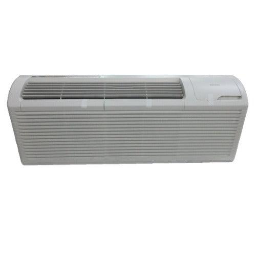
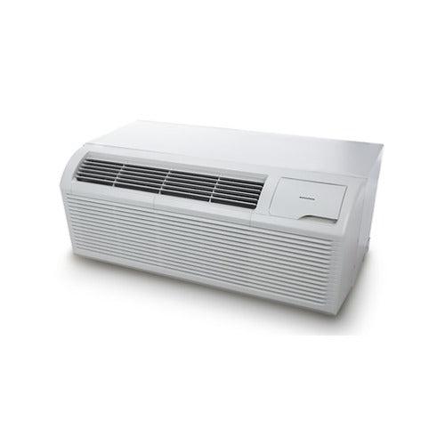
Older homes, additions, and finished attics often need mixed strategies. Use room-level loads to decide whether to extend ducts or add dedicated equipment. Tight closets or roof restrictions point to PTACs. Ceiling constraints? Consider low-profile concealed-duct mini-splits.Keep refrigerant line length and elevation within the manufacturer’s spec to preserve capacity; order correct line sets and accessories.
When retrofitting, measure actual return openings and grille free area; inadequate return often masquerades as “undersized equipment.”
Code, Rebates, and Documentation: Getting It Approved
Some jurisdictions and rebate programs require a certified Manual J report. Even if not required, documentation helps future service and resale. Save your calculator report, envelope assumptions, and equipment selection sheets.
Pair Manual J with Manual S (equipment selection) and Manual D (duct design) where ducts are involved to satisfy plan reviewers.
Need a stamped submittal package? Start with our Design Center. Our Return Policy and Lowest Price Guarantee protect the purchase process.
Troubleshooting Conflicting Results from Different Calculators
If two diy-load-calculator-tools disagree, isolate differences in:
-
Weather station/design temp
-
Infiltration assumptions
-
Window SHGC/U-factor defaults
-
Duct location/loss factors
-
Internal gains and occupancy schedules
Run a controlled A/B: keep all inputs identical and vary one category at a time. The delta points to the culprit. When in doubt or if code documentation is needed escalate to a professional Manual J via the Design Center or upload photos for review using Quote by Photo.

