Few things make homeowners feel more intimidated than opening a furnace panel and seeing a maze of wires staring back at them. I hear it all the time: I found the furnace wiring diagram, but I have no idea what I’m looking at. Or I searched for an HVAC wire diagram and now I’m more confused than when I started. And honestly? That reaction makes complete sense.
Whether you’re dealing with a gas or electric system, furnace wiring is where comfort, safety, and control all intersect. Every thermostat signal, every safety switch, every blower motor command flows through those wires. That’s why questions about a furnace wiring diagram, furnace wiring schematic, or furnace control board wiring diagram usually come up when something isn’t working—or when someone is trying to understand why it works the way it does.
Today, I want to pull back the curtain on furnace wiring in a way that feels approachable, not overwhelming. We’ll talk about basic furnace wiring diagrams, compare gas furnace wiring diagrams with electric furnace wiring diagrams, and explore how modern systems like the Goodman MBVK electric furnace simplify wiring, troubleshooting, and long-term reliability.
Why Furnace Wiring Diagrams Matter More Than You Think
A furnace wiring diagram isn’t just a technical drawing—it’s a roadmap. It shows how power moves through the system, how the thermostat communicates with the furnace, and how safety devices protect your home.
When technicians troubleshoot a furnace, one of the first things they consult is the furnace wire diagram. That diagram tells them:
-
Where voltage should be present
-
Which components should be communicating
-
What happens when the thermostat calls for heat
For homeowners, understanding even a basic furnace wiring diagram can make conversations with contractors clearer and help you better understand your system’s capabilities and limitations.
The Big Picture: What an HVAC Wire Diagram Represents
An HVAC wire diagram typically shows how heating, ventilation, and sometimes cooling components interact. In a forced-air system, that includes:
-
The thermostat
-
The furnace control board
-
The blower motor
-
Safety switches
-
Power supply
In other words, a wiring diagram is the nervous system of your heating equipment. And the complexity of that nervous system depends heavily on whether your furnace is gas or electric.
Gas Furnace Wiring Diagram vs. Electric Furnace Wiring Diagram
This is where things get interesting.
A gas furnace wiring diagram has to account for:
-
Ignition systems
-
Gas valves
-
Flame sensors
-
Pressure switches
-
Venting safety controls
Each of these components requires wiring, monitoring, and fail-safe logic. That’s why a gas furnace wiring schematic often looks intimidating—there are simply more parts involved.
An electric furnace wiring diagram, by comparison, is far more streamlined. There’s no ignition sequence, no flame verification, and no gas valve logic. Power flows to electric heating elements, airflow is managed by the blower motor, and the control board coordinates everything.
This difference is one of the reasons the Goodman MBVK electric furnace is such a reliable system—it eliminates entire categories of wiring complexity.
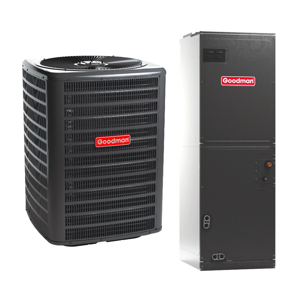
Inside the Goodman MBVK Electric Furnace Wiring
The MBVK is an electric air handler designed to work with electric heat kits and heat pumps. Its wiring layout reflects modern HVAC priorities: efficiency, clarity, and compatibility.
If you were looking at an electric furnace diagram for the MBVK, you’d notice:
-
A clearly defined low-voltage section for thermostat wiring
-
High-voltage connections isolated for safety
-
A centralized control board managing operations
Goodman’s official MBVK product documentation highlights how the unit is engineered for clean installation and straightforward service access—something both technicians and homeowners appreciate.
Furnace Control Board Wiring Diagram: The Brain of the System
The furnace control board wiring diagram is arguably the most important schematic in any modern furnace. This board receives signals from the thermostat and sends instructions to:
-
The blower motor
-
The heating elements
-
Safety sensors
In gas furnaces, control boards must manage ignition timing and flame verification. In electric systems like the MBVK, the board’s job is more direct—responding quickly to heating demands without juggling combustion-related safety checks.
This simplicity reduces failure points and makes diagnosing issues faster and more accurate.
Electric Furnace Thermostat Wiring: What Those Letters Really Mean
One of the most common wiring questions I hear involves electric furnace thermostat wiring. Homeowners see labels like R, C, W, Y, and G and wonder what they all do.
In an electric furnace setup:
-
R provides power
-
C completes the circuit
-
W signals heat
-
G controls the blower
-
Y often connects to a heat pump or cooling system
Because electric furnaces don’t need to manage gas ignition, thermostat wiring tends to be cleaner and more consistent. That consistency makes system upgrades—like adding a smart thermostat—much easier.
Resources like ENERGY STAR’s thermostat and HVAC guidance explain how proper wiring improves efficiency and system communication.
Forced Air Furnace Wiring Diagram: Airflow Is Everything
A forced air furnace wiring diagram emphasizes airflow control. No matter how heat is generated, moving that heat efficiently is critical.
In the MBVK, airflow is managed by a variable-speed ECM blower motor. The wiring supports:
-
Multiple fan speeds
-
Smooth ramp-up and ramp-down cycles
-
Continuous fan options for air circulation
This advanced motor control is one reason electric furnaces can feel more comfortable—they don’t rely on abrupt on/off cycles.
Basic Furnace Wiring Diagram: What Homeowners Should Recognize
While you should never attempt complex wiring changes yourself, understanding a basic furnace wiring diagram helps you recognize the major components:
-
Incoming power
-
Transformer
-
Control board
-
Blower motor
-
Thermostat connections
Knowing these basics can help you describe issues accurately and avoid misunderstandings when discussing repairs or upgrades.
Educational breakdowns like Modernize’s explanation of furnace operation are helpful for visualizing how wiring supports overall system function.
Electric Furnace Wiring Schematic: Fewer Wires, Fewer Problems
An electric furnace wiring schematic reflects one of the biggest advantages of electric heat: reduced complexity.
Because there’s no combustion, electric furnaces don’t need:
-
Flame rollout switches
-
Pressure switch circuits
-
Venting interlocks
That means fewer wires, fewer connectors, and fewer things that can fail. Over time, that simplicity translates into fewer service calls and more predictable performance.
Gas Furnace Wiring Schematic: Why Complexity Increases Risk
A gas furnace wiring schematic exists for good reason—safety. But each added safety device introduces another potential failure point.
Loose connections, aging sensors, and environmental factors like moisture or dust can all interfere with these circuits. When that happens, the furnace may shut down even if the core heating components are still functional.
This is one reason homeowners with older gas systems often feel like they’re constantly chasing electrical gremlins.
Troubleshooting Through the Wiring Diagram
When a technician diagnoses a problem, they often start at the wiring diagram and follow the logic path:
-
Did the thermostat send a signal?
-
Did the control board respond?
-
Did power reach the heating element or motor?
In electric systems like the MBVK, this process is usually faster because there are fewer conditional steps. That efficiency benefits homeowners through reduced labor time and clearer explanations.
Consumer-focused resources like Consumer Reports’ HVAC buying guides often highlight system simplicity as a key factor in long-term satisfaction.
Why Wiring Simplicity Matters for Long-Term Ownership
Most homeowners don’t think about wiring until something breaks. But the design of a furnace’s wiring affects:
-
Reliability
-
Repair costs
-
Upgrade compatibility
A cleaner furnace wiring schematic means fewer surprises down the road. It also means your system is better prepared for future technologies, like advanced thermostats or home automation integrations.
The Goodman MBVK’s wiring architecture reflects this forward-thinking approach.
When to Look at the Diagram—and When Not To
I’ll say this clearly: furnace wiring diagrams are tools for understanding, not invitations to experiment. If you’re experiencing issues, reviewing the diagram can help you ask better questions—but actual repairs should be left to licensed professionals.
That said, knowledge is empowering. When you understand how your system is wired, you’re less likely to feel overwhelmed or taken advantage of.
Final Thoughts from Me to You
Wires may not be the most glamorous part of your heating system, but they’re among the most important. A furnace wiring diagram tells the story of how comfort is delivered, how safety is maintained, and how technology comes together behind the scenes.
The Goodman MBVK electric furnace tells a particularly reassuring story—one of clarity, simplicity, and modern design. By reducing wiring complexity and eliminating combustion-related circuits, it offers homeowners a system that’s easier to understand, easier to maintain, and easier to trust.
And sometimes, peace of mind really does come down to knowing that fewer wires mean fewer worries.