Wiring & Electrical Basics for Central AC (DIY + When to Hire a Pro)
Wiring a central air conditioner looks deceptively simple—two hot legs to a contactor, a thermostat cable, maybe a whip, and a disconnect—and yet the details determine whether your system starts cleanly, runs efficiently, passes inspection, and stays safe for the long haul. This guide walks you through the practical, step-by-step flow for the outdoor condenser circuit (breaker → disconnect → whip → terminations), the indoor equipment circuit (air handler or furnace/coil), and the thermostat/low-voltage controls. We’ll also cover pre-power safety checks, commissioning measurements, common mistakes to avoid, and clear cues for when to hand it off to a licensed pro.
The Big Picture: Two Electrical Systems and One Comfort System
A ducted AC (or an AC + furnace/air handler combo) is driven by two separate electrical systems:
-
Line (high) voltage, which powers the outdoor condenser (typically 240 V) and the indoor blower/air handler or furnace (120 or 240 V, depending on model). This circuit requires correctly sized overcurrent protection, conductors, bonding/grounding, a service disconnect within sight of the outdoor unit, and proper terminations torqued to spec.
-
Control (low) voltage, the 24 V thermostat, and the equipment control circuit. This is where R, C, Y1/Y2, G, W, O/B live. It carries signals, not power for motors; miswires here won’t usually electrocute you—but they routinely cause nuisance calls, board damage, and strange staging behavior.
Think of them as two projects with different rules and tools; don’t blur the boundaries. When you plan the install, treat each system as a dedicated task with its own checklist.
Safety First (Non-Negotiable)
Electricity turns small mistakes into big ones fast. Do these before you touch a conductor:
-
De-energize at the service panel and lock/tag the breaker so nobody re-energizes the circuit while you work. Verify de-energized at the work location with a non-contact voltage tester and then a meter on known points.
-
PPE and posture: Safety glasses, insulated gloves, and a tidy workspace. If you ever must measure in a live cabinet (pros only), standalone on dry ground, and keep one hand behind your back to avoid current paths through your chest.
-
Respect enclosure ratings: Use NEMA-rated outdoor boxes and fittings; rain carries straight into shortcuts.
-
Know your limits: Service panel modifications, aluminum wiring, new sub-panels, and rooftop equipment are sensible hand-off points for a licensed electrician or HVAC pro.
Nameplate 101: MCA & MOCP (How You Choose Breaker and Wire)
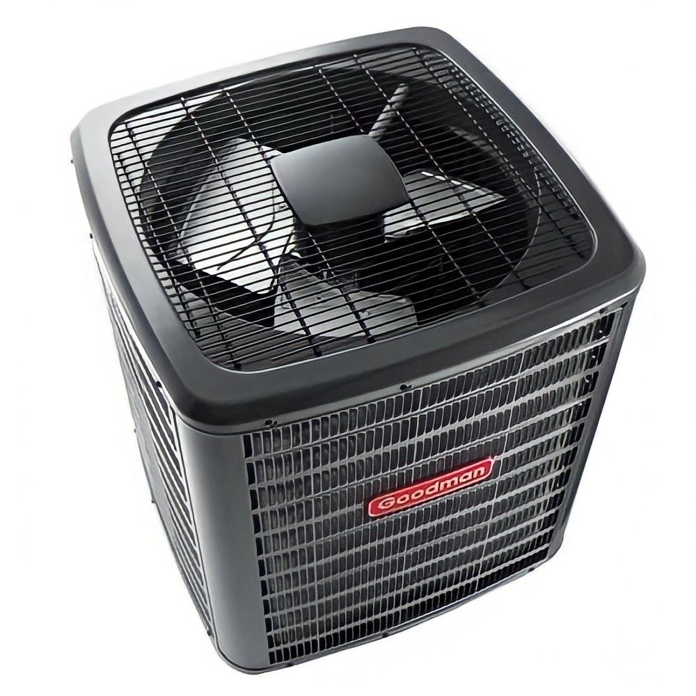
On the outdoor unit’s data plate, you’ll find two numbers that govern the entire branch circuit:
-
MCA (Minimum Circuit Ampacity): the minimum conductor ampacity required for the circuit. This, together with conductor temperature ratings and installation conditions, informs the wire gauge you must pull.
-
MOCP/MOP (Maximum Overcurrent Protection): the largest breaker or fuse permitted for the equipment. Your breaker must be at or below MOCP, your conductor ampacity at or above MCA, and your conductor insulation compatible with termination temperature ratings (e.g., 60 °C/75 °C lugs).
When the manual and the nameplate disagree, the manufacturer’s installation manual wins for that specific model (it embeds the tested combinations and torque specs). The research and field literature reiterate that following manufacturer instructions—especially on electrical protection and airflow—is foundational to real-world performance and longevity. ➜ Research Gate: Enhancing Safety: The Challenge of Foresight
Step-by-Step: Outdoor Condenser Circuit (Breaker → Disconnect → Whip → Terminations)
1) Install the Panel Breaker
-
With the main off and the dead-front removed, install a listed two-pole breaker sized to the unit’s MOCP and approved for your panel model.
-
Dress conductors to code, avoid overcrowding knockouts, and torque breaker lugs and neutral/ground terminations to the manufacturer’s spec.
-
Label the breaker “AC CONDENSER” with a durable panel directory entry; this matters for future service and inspections.
2) Run the Branch Circuit
- Pull conductors that meet or exceed MCA using an approved wiring method for the space (EMT/IMC with THHN/THWN, MC cable, etc.).
-
Support and protect per code: strap intervals, bushing at sharp edges, proper connectors, and clearances to gas/water piping.
3) Mount the Outdoor Disconnect
-
Install a weather-rated, visible-blade disconnect within sight of the condenser (not hidden behind it), at a workable height.
-
Many AC/HP units call for a fusible pull-out—match the manual (don’t guess). The purpose is safe, local isolation and, when fusible, a properly coordinated short-circuit path. Correct placement and device type are emphasized throughout safety and product standards discussions in the electrical literature.
4) Whip the Final Connection
-
Run liquid-tight flexible conduit from the disconnect to the unit with the right fittings, a drip loop, and a properly sized equipment grounding conductor (EGC) pulled with the circuit conductors.
-
Avoid tight bends at cabinet entries; keep the whip short but serviceable; don’t stretch across footpaths or create snags.
5) Make the Terminations (and Bond)
-
Land L1/L2 on the line side of the contactor (or per the inverter board terminals), bond the EGC to the ground bar/chassis, and torque all lugs to the equipment spec with a calibrated tool.
-
Confirm factory wiring is intact, ferrules and spades are tight, and no conductors are nicked under clamp screws.
6) Line-Voltage Pre-Power Checks
-
Tug test every conductor and check that the disconnect operates smoothly.
-
Visually verify clearances to refrigerant lines, wire abrasion points, and rain paths.
-
Replace covers fully—missing screws are water paths.
Step-by-Step: Indoor Equipment Circuit (Air Handler or Furnace/Coil)
Your indoor unit may be a dedicated air handler (often 240 V with an ECM blower) or a gas furnace with an evaporator coil (typically 120 V for the blower and controls). Wire this as a separate branch circuit per the nameplate and manual.
-
Breaker & conductors: Size to indoor equipment MCA/MOCP and match the termination temperature rating.
-
Service switch: Provide a service switch (or a listed disconnect) within sight of the indoor unit; attics often require a light and a receptacle on the same platform.
-
Condensate safety: Wire any float switches in series with Y (or as the manufacturer specifies) so a blocked drain trips the cooling call.
-
Bonding and neutrals: Keep neutral and ground isolated in sub-panels; use listed bars and one conductor per hole unless specifically rated for two.
Step-by-Step: Thermostat & Low-Voltage Wiring (24 V Controls)
Typical Terminals (Conventional AC + Furnace)
-
R = 24 V hot from transformer
-
C = common (required for most smart thermostats)
-
Y1 / Y2 = cooling stage 1 / stage 2
-
G = indoor blower
-
W = heat call (furnace)
-
O/B = heat-pump reversing valve (O = cool-energized, B = heat-energized)
Cable & Routing
-
Use 18/5 or 18/8 thermostat cable with enough spare conductors for staging and accessories. Avoid running parallel to line voltage; cross at 90° to limit induced noise. Protect cable where exposed (conduit, guard plates).
At the Thermostat
-
Level the base, pull a service loop (4–6 in), and land conductors by equipment type (conventional vs. heat pump). Provide a robust C-wire for smart thermostats; power-stealing tricks often cause nuisance dropouts.
At the Air Handler/Furnace
-
Land R/C from the transformer, G to blower, Y1/Y2 out to the condenser, W to heat. For communicating systems, use only the manufacturer’s bus and terminations; never mix conventional 24 V with proprietary comm terminals.
At the Condenser (Control Block)
-
Land Y1 (and Y2, if staged) and C at the low-voltage block or the inverter control. Confirm factory low-voltage leads at the contactor coil are tight and undamaged.
Low-Voltage Functional Checks
-
With power on, meter 24 V between R and C at the handler; on a cooling call, verify 24 V at Y1 and across the contactor coil (or inverter input). Many commissioning guides emphasize these simple checks because they prevent the majority of “no-cool after install” callbacks. ➜ Carrier: 25VNA8-24VNA9-4SM
Grounding, Bonding, and Surge Protection
-
Bond every cabinet with a continuous equipment grounding conductor sized to the circuit; do not rely on conduit alone unless it is an approved grounding path with listed fittings.
-
In sub-panels, isolate neutral and ground; never double-lug neutrals unless the bar is listed for it.
-
Consider a Type 1/2 surge protective device (SPD) at the service or HVAC sub-panel to protect ECM blowers and inverter boards from transients. A small investment here can save control boards when the grid hiccups.
Commissioning Electrical: Quick Tests That Save Hours Later
A clean electrical start-up is half visual, half measurements:
-
Visual quality audit
-
Are all covers on? Any unused knockouts open? Is drip-looping correct? Are cable jackets intact up to the clamp?
-
Are labels complete (panel, disconnect, unit sticker)?
-
-
Torque & tug
-
Torque every termination to nameplate or panel spec; then tug-test conductors.
-
-
Voltage checks
-
Confirm L-L and L-G at supply and load sides of the disconnect; look for sag under compressor inrush (inverter units should ramp smoothly).
-
-
Thermostat mode tests
-
Call for cool; verify outdoor unit starts, indoor blower ramps per profile, and no breaker trips.
-
If dual-fuel or heat pump, confirm reversing valve logic (O/B) and that heat calls do not back-feed cooling circuits.
-
-
Document readings
-
Panel breaker size, conductor size/insulation, MCA/MOCP, line voltage, control voltage, and any staging/thermostat settings. A tidy startup log is worth its weight later.
-
The Most Common Wiring Mistakes (and the Better Move)
-
Oversizing the breaker beyond MOCP
-
Bigger is not safer here; it can delay the trip on faults that the equipment was tested to handle. Follow MOCP and the installation manual’s table.
-
-
Undersizing wire vs. MCA or ignoring termination temperature ratings
-
Ampacity in the table assumes a temperature rating; match conductor insulation and lug rating (60/75 °C) correctly.
-
-
Skipping the disconnect or putting it out of reach
-
It must be within sight of the unit and usable at a safe working height; don’t bury it behind the condenser.
-
-
No EGC in the whip
-
Always pull a properly sized ground; do not assume bonding through flexible metallic conduit unless the product is listed and continuous.
-
-
Thermostat miswires
-
The classics: Y2 on the wrong terminal, missing C-wire, or reversed O/B on heat pumps. Double-check the schematic before applying power. ➜ NREL: AC Diagnostics, Maintenance, and Tune-Up Procedures
-
-
Mixing conventional 24 V with communicating terminals
-
This can cook boards; never land conventional wires on proprietary comm ports.
-
-
Ignoring manufacturer torque specs
-
Loose lugs lead to nuisance trips and heat; over-torqued lugs damage strands and threads.
-
-
Forget the condensate float
-
Wire the float to break Y (as specified) so a backed-up drain stops cooling before it overflows.
-
When to DIY vs. When to Hire a Pro
DIY is reasonable when:
-
You’re replacing a like-for-like condenser on an existing, properly sized circuit and disconnect.
-
You’re running a short, straightforward branch circuit in an accessible area and are comfortable with panel work under permit.
-
You’re landing thermostat conductors on a conventional (non-communicating) system and can follow a diagram.
Hire a pro when:
-
You need a panel upgrade, a new sub-panel, or you’re dealing with aluminum branch circuits.
-
The unit is rooftop-mounted or requires structural/roofing coordination.
-
It’s a communicating/inverter system; miswires can nuke expensive boards.
-
Your jurisdiction requires inspection, and you’re not experienced with electrical code details.
-
You want a turn-key commissioning (airflow + electrical + refrigerant) with documentation.
Deeper Context: Why Electrical Details Affect Comfort, Too
It’s easy to think of wiring as a pass/fail check—either the fan spins or it doesn’t. In practice, electrical quality interacts with comfort in subtle ways:
-
Voltage drop/inrush and poor connections increase heat at terminals, cause nuisance trips, and can complicate compressor starts—leading to short cycling and poor humidity control.
-
Inaccurate staging setup at the thermostat or control board turns a premium variable-speed system into a one-speed clunker.
-
Skipping disconnects and sloppy routing make future service harder; hard service means shortcuts later, which often show up as comfort complaints.
The research literature is full of field studies showing that “installation faults” (including electrical and control issues) reduce real-world performance compared to rated values; nailing basic electrical/controls commissioning is part of closing that gap. ➜ DOE Residential HVAC Installation Literature Review (2018)
A Commissioning Checklist You Can Hand to Your Installer
-
Panel & branch circuit: breaker size vs. MOCP checked; conductor ampacity vs. MCA checked; terminations torqued; labels updated.
-
Outdoor disconnect: within sight; correct type (fusible or non-fusible) per manual; rain-tight; whip drip-looped and supported.
-
Indoor equipment: service switch within sight; float switch wired; neutral/ground isolation verified in sub-panels.
-
Thermostat & low voltage: 24 V confirmed; Y1/Y2 calls reach condenser/inverter board; C-wire solid; reversing valve logic verified.
-
Voltage quality: line voltage under load; inrush behavior observed; no nuisance trips.
-
Documentation: record model/serials, MCA/MOCP, breaker size, wire size/insulation, torque values, and thermostat programming (staging thresholds, blower ramps).
-
Final safety: all covers on, sharp edges bushed, unused knockouts closed, clearances maintained.
Frequently Asked Questions
Do I really need a disconnect within sight?
Yes—safe service requires a local means of isolation that the tech can see and control. It’s not optional, and it’s not scenery.
Can I reuse my old whip and disconnect?
Only if the ampacity, condition, and listing match the new equipment’s needs—and the whip isn’t brittle or waterlogged. Replacing these parts is cheap insurance.
What if I only have four wires to the thermostat?
If you’re adding a smart thermostat or staging, you likely need a C-wire and possibly more conductors; consider pulling new cable rather than relying on add-a-wire gadgets.
Will a whole-home surge protector really help?
It won’t stop a direct lightning strike, but it can blunt everyday transients that stress ECM motors and boards. For inverter systems, it’s a wise add-on.
Where This Fits in Your Bigger HVAC Strategy
Good wiring won’t fix a poorly sized or poorly ducted system, but it’s a pillar of reliable operation. Pair clean electrical work with Manual J/S/D, sealed and balanced ducts, and a documented startup—and you’ll get the quiet, even, dry comfort you paid for from your central air conditioning systems.
In the next blog, we will have more knowledge about "Air Conditioner Outlet Types and Power Compatibility Guide".

