Sizing Fundamentals: Tons, BTUs, and Required Airflow
Cooling capacity is expressed in tons (1 ton = 12,000 BTU/h). Typical homes use 1.5–5 tons (18,000–60,000 BTU/h). Airflow must track cooling load: target ~400 CFM per ton (±10%). That means a 3-ton system expects ~1,200 CFM through the coil at rated external static pressure (ESP). The furnace’s heating capacity (input × AFUE = output BTU/h) should be proportional to the home’s load and the blower’s ability to move design CFM across both heat exchanger and evaporator.
Quick math:
CFM_target ≈ Tons × 400
BTU_cooling ≈ Tons × 12,000
Some specialty applications tweak airflow: ~350 CFM/ton for latent-heavy climates (more dehumidification), up to ~450 CFM/ton where sensible load dominates or ducts are exceptionally well designed.
Explore equipment: Furnaces
Why Matching Matters: Energy, Comfort, and Cost
Oversized cooling short-cycles: it hits setpoint fast but doesn’t pull moisture long enough leading to clammy rooms, temperature swings, and higher kWh. Undersized equipment runs nearly nonstop and still may miss setpoint, burning energy and wearing components. Mismatch penalties are real: energy waste, callbacks, and reduced SEER2 realization in the field.
Symptoms of mismatch:
• Oversize: short cycles, cold supply/clammy rooms, high RH, noisy starts
• Undersize: continuous run, warm rooms, long pull-down times
Improper pairing can drive 20–30% higher energy use versus a properly sized and commissioned system. Balanced capacity + airflow lets the equipment operate in its “design window,” where coils exchange heat effectively and controls behave predictably.
Learn more: Sizing Guide
Blower CFM Targets and What Happens When You Miss
Your blower must deliver design CFM through the real ESP of the duct system and coil. Below ~350 CFM/ton, coil surface gets too cold and risks frost/ice because not enough heat is presented to the refrigerant. Above ~450 CFM/ton, air leaves the coil too warm for good latent removal, so RH stays high even when the thermostat is satisfied.
Design targets at nominal ESP:
• 350–450 CFM/ton acceptable range
• 400 CFM/ton preferred baseline
• Verify CFM via external static + fan table OR flow grid/traverse
A correct blower tap (or ECM profile) is only half the battle—clean filters, a properly metered coil, and low-loss returns are just as critical. Document airflow at commissioning so you can defend performance later.
Accessories: Filters & parts
Blower Motor Strategy: Single-Stage, Multi-Speed, and Variable-Speed
Match motor capability to the furnace and comfort goals. Single-stage furnaces pair well with single- or multi-speed blowers. Two-stage/variable furnaces shine with ECM variable-speed motors that hold target CFM across changing ESP, enabling better dehumidification and quieter ramps.
Selection cues:
-
PSC (permanent split capacitor): Simple, lower cost, fixed speeds, less efficient.
-
ECM (electronically commutated): Higher efficiency, pressure-responsive CFM, programmable profiles (dehumidify, comfort ramps).
Use dehumidification profiles (e.g., “comfort-E” or 350–375 CFM/ton in first stage) during shoulder seasons to extend coil contact time and squeeze out moisture.
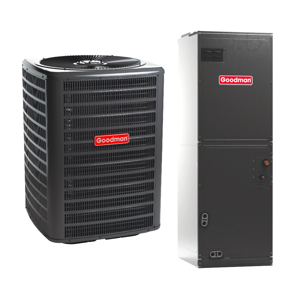
Browse matched systems: R-32 AC + Gas Furnace bundles
Evaporator Coil: Capacity, Geometry, and Materials
Coil tonnage should match or be slightly greater than the condenser. A small “assist” (up to ~+0.5 ton) can provide extra surface area for heat transfer without compromising control—beyond that, short cycling and poor latent removal become likely. Geometry matters: fin density, circuiting, and face area set pressure drop and heat exchange.
Coil fit guide:
Condenser 2.5T → Coil 2.5–3.0T (verify TXV and subcool targets)
Keep ΔT sensible/latent in spec and watch static across the coil.
Materials:
-
Copper tubes/aluminum fins: Excellent thermal conductivity, serviceable, higher cost.
-
All-aluminum: Lighter, good corrosion resistance, often lower cost; ensure clean coil protocols.
Shop coils: R-32 Coils
Refrigerant & Metering: TXV/TXV Sizing and R-32 Compatibility
The expansion device must be sized to the coil capacity and the refrigerant. Undersized TXVs starve the coil (low SH, low capacity); oversized can flood circuits, threaten compressors, and disrupt superheat control. With R-32 systems, use coils and TXVs designed and rated for R-32’s pressure/temperature characteristics and required labeling/safety provisions.
Commissioning checkpoints:
• Verify TXV tonnage & refrigerant match
• Set superheat/subcool to OEM targets
• Confirm line set size/length within spec
Humidity, IAQ, and the Comfort Envelope
Comfort isn’t just temperature. Maintain ~30–50% RH for health, comfort, and materials. Correct sizing plus correct CFM enables long, stable cycles that condense moisture on the coil. Oversize the condenser or push CFM too high and you’ll meet a setpoint while leaving RH elevated—classic “cool but clammy.”
Simple mapping:
• Too high RH → reduce airflow or staging, check TXV & charge
• Too low RH (winter) → humidification/air sealing strategies
Use dehumidify-on-demand control to temporarily reduce blower CFM during part-load cooling, improving latent capacity without hardware changes. Log coil ΔT and return/supply RH for proof.
Explore alternatives: Ductless for zone humidity control
Duct Design, ESP, and Measured Airflow
Even perfectly matched equipment underperforms with restrictive ducts. Use Manual D to size trunks/branches for the design CFM at a realistic ESP target (commonly 0.5 in.w.c. total external static, but follow OEM limits). Balance with dampers, ensure generous returns, and keep filters/coils clean.
Commission like a pro:
1) Measure total external static (TESP)
2) Compare to blower table for estimated CFM
3) Spot-check with flow grid or traverse
4) Investigate high-loss sections (tight returns, undersized boots)
Each 0.1 in.w.c. you shave off ESP, buy back CFM and cut blower watts—especially with ECMs.
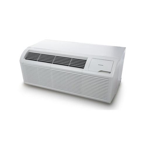
Need packaged options? Residential packaged AC
Professional Workflow: Manual J, S, and D—Plus a Field Checklist
-
Manual J: Calculate heating/cooling loads from envelope, orientation, infiltration, and internal gains.
-
Manual S: Select equipment that meets the net sensible & latent loads near design conditions; verify blower CFM range covers your target.
-
Manual D: Design duct system to deliver design airflow quietly and efficiently.
Field checklist:
-
Confirm load (J) and select matched equipment (S).
-
Choose coil/TXV by refrigerant and tonnage.
-
Set blower profile for target CFM/ton.
-
Verify TESP, estimate CFM from tables, and spot-measure.
-
Charge by subcool/superheat per OEM; verify SH/SC after steady state.
-
Document ΔT (air), RH, and room-by-room airflow.
Resources: Design Center
Matched Systems Quick-Spec Map (With Product Paths)
Use this as a starting cross-check final selection must follow Manual J/S/D and OEM data.
|
Condenser Tons |
Target CFM |
Coil Size* |
Furnace Blower Range |
Typical Heat Output** |
Product Paths |
|
1.5T |
~600 |
1.5–2.0T |
600–800 CFM |
40–60k BTU |
|
|
2.0T |
~800 |
2.0–2.5T |
800–1,000 |
60–80k |
|
|
2.5T |
~1,000 |
2.5–3.0T |
1,000–1,200 |
70–90k |
|
|
3.0T |
~1,200 |
3.0–3.5T |
1,200–1,400 |
80–100k |
|
|
3.5T |
~1,400 |
3.5–4.0T |
1,400–1,600 |
90–110k |
|
|
4.0T |
~1,600 |
4.0–4.5T |
1,600–1,800 |
100–120k |
|
|
5.0T |
~2,000 |
5.0–5.5T |
1,900–2,200 |
120–140k |
* Keep oversize ≤ ~0.5 ton unless OEM guidance says otherwise.
** Heat output ranges vary by AFUE and altitude; verify OEM blower tables for CFM at your TESP.
DIY Ductless Mini-Splits for zoned applications for supplemental cooling, and Financing if timing matters.
Call to Action: Get a Matched System Spec You Can Trust
Ready to lock in the right pairing and avoid callbacks? Start with a load calc and airflow plan:
-
Share your details via the Design Center or send photos for a quick review.
-
Tell us your targets: tonnage, SEER2, fuel type, and any humidity or noise constraints.
-
We’ll point you to specific, compatible equipment condenser, furnace/air handler, coil, TXV, and line set from our matched inventory: Matched R-32 Systems.
Typical field questions we’ll answer up front:
-
Will the blower maintain 400 CFM/ton at my measured static?
-
Is the coil/TXV correctly sized for R-32 and my condenser?
-
How will staging/ECM profiles be set for humidity control?
-
What’s the expected ΔT and RH at design?
If you want a second set of eyes on your Manual J/S/D or a check on blower tables and ESP, reach out: Contact Us. We’ll help you spec a matched system that performs the way it should on paper and in the field.

