Heat Gain vs. Heat Loss Why Both Matter in Sizing
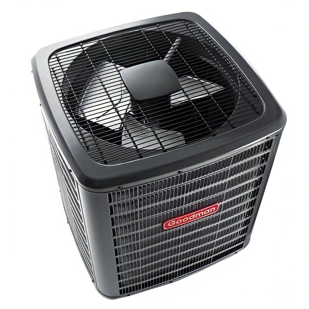
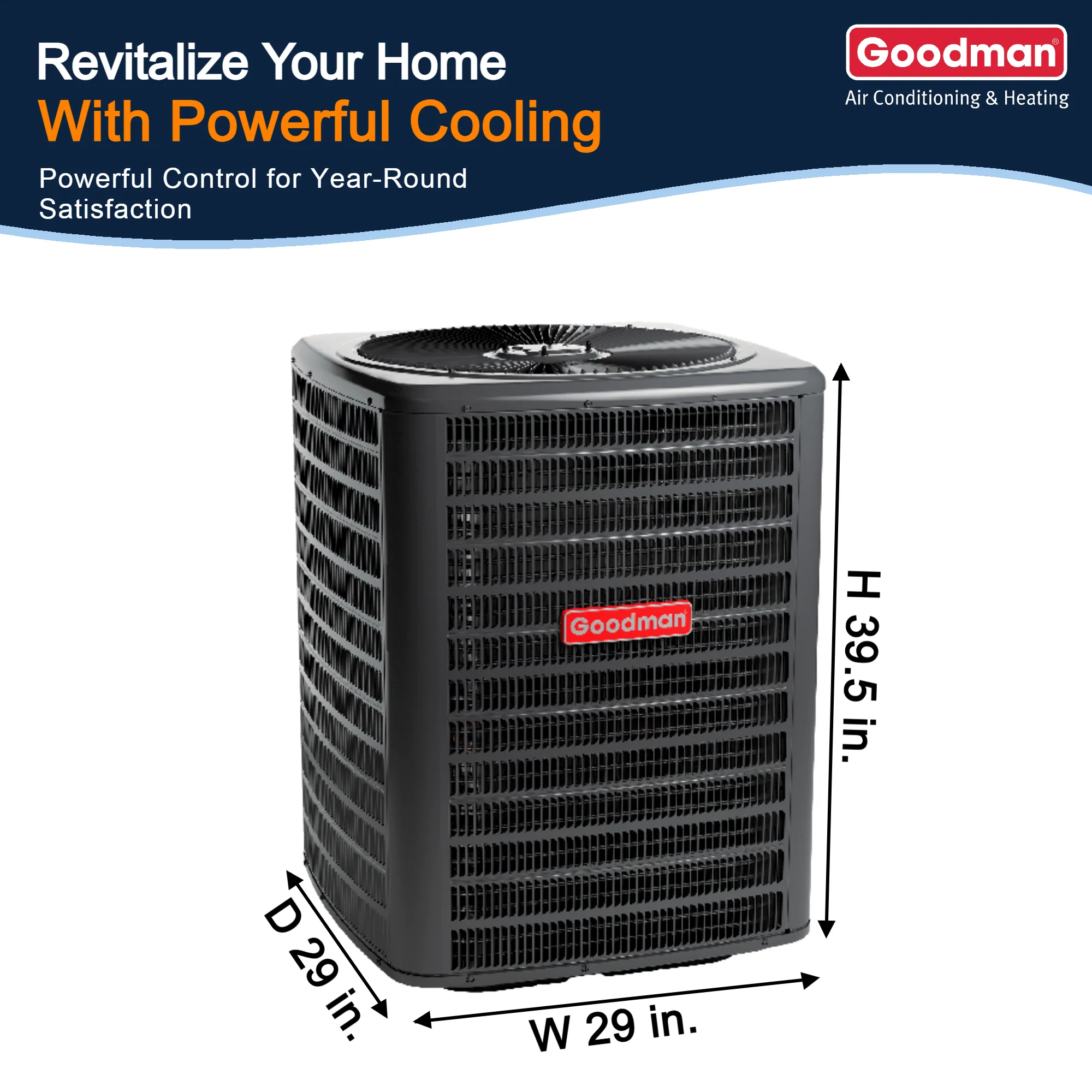
Heat gain is the sum of thermal inputs the cooling system must remove in hot weather (solar, occupants, lighting/equipment, infiltration, conduction). Heat loss is the thermal energy the building sheds in cold weather that the heating system must replace. Manual J requires both because a home that peaks at 2.5 tons sensible in July might only need 38–45 kBTU/hr heat in January or vice versa. Ignoring either risks short cycling (oversized cooling) or failure to maintain setpoint (undersized heating). Pros know that envelope, orientation, occupancy patterns, and ventilation/infiltration can shift loads dramatically. If you’re speccing equipment families, compare across solutions like R-32 condensers to match load profiles and control strategy.
The Core Conduction Equation You Use Every Day
Manual J’s envelope math starts with:
Q = U × A × ΔT
Where Q = BTU/hr, U = overall heat transfer coefficient (BTU/hr·ft²·°F), A = area (ft²), ΔT = indoor–outdoor temp difference (°F). Example: a 200 ft² wall, U = 0.5, ΔT = 40°F → Q = 0.5 × 200 × 40 = 4,000 BTU/hr heat loss. Repeat for windows, roof, floors, and sum. In cooling season, the same equation quantifies conduction heat gain when outdoor air is hotter than inside.
Quick visual:
[Outdoor 100°F] → | U * A * ΔT | → [Indoor 75°F]
Tightening the assembly (lowering U via better insulation or windows) often trims enough load to right-size from 3.0 tons to 2.5 tons. Pair envelope upgrades with variable-speed air handlers for finer control: Air Handlers.
Where Cooling Load Comes From (and How to Quantify It)
Cooling load aggregates solar gain, internal gains, infiltration, and conduction. Solar arrives through glazing and sun-struck surfaces. Internal gains include people, lighting, electronics, and appliances; every kWh ends up as heat (~3,413 BTU). Commercial offices with dense plug loads often see internal gain dominate afternoons.
At-a-glance sources
-
Solar: glazing SHGC, orientation, shading.
-
Internal: occupants (~230–300 BTU/hr sensible + latent each), lighting/equipment (convert watts to BTU/hr).
-
Infiltration: warm, humid air sneaking in.
-
Conduction: U-values × areas × ΔT.
Workflow visual:
Total Cooling = Conduction + Solar + Internal + Infiltration
For equipment pairing and coil selection, browse: R-32 Condensers or small-zone DIY Ductless.Best Air Conditioners.
Sensible vs. Latent Loads Psychrometrics in Plain English
Sensible loads change air temperature (°F) without changing moisture content. Latent loads address moisture (condensing water vapor) with little temp change. On a psychrometric chart, sensible travel is horizontal (left/right), latent is vertical (up/down).
Mini-chart sketch:
Humidity ↑
| Latent (vertical)
|
Temp → +----------------------→
Sensible (horizontal)
Why it matters: 75°F at 20% RH feels comfortable; 75°F at 90% RH feels clammy. A system that only has sensible capacity will miss comfort. Coil selection, airflow (CFM/ton), and fan speeds set your Sensible Heat Ratio (SHR). For humid climates or infiltration-prone homes, prioritize equipment with robust latent capacity: Ductless Wall-Mounted Systems shine at moisture control with staged/variable operation.
The Three Equations You’ll Actually Use in the Field
Sensible:
Qs (BTU/hr) = 1.08 × CFM × ΔT
Latent:
Ql (BTU/hr) = 0.68 × CFM × ΔW
(ΔW in grains of moisture per lb dry air)
Total by enthalpy:
Qt (BTU/hr) = 4.5 × CFM × Δh
(Δh = enthalpy change, BTU/lb)
Example: 800 CFM, ΔT = 18°F → Qs = 1.08×800×18 = 15,552 BTU/hr. If ΔW = 30 gr/lb → Ql ≈ 0.68×800×30 = 16,320 BTU/hr. With Δh = 6 BTU/lb → Qt = 4.5×800×6 = 21,600 BTU/hr (note: not simply Qs + Ql if measured at different states). Use the method that matches your instrumentation—thermometer + hygrometer (ΔT/ΔW) or enthalpy probes.
Dial in airflow with static pressure and blower tables for accurate CFM; then verify coil leaving conditions to confirm latent performance. Need matched coils/handlers? See and Air Handlers.
Infiltration: The Load You Don’t See but Always Pay For
Uncontrolled outdoor air through cracks, gaps, and unsealed penetrations can represent a large share (up to ~30%) of heating/cooling energy loss. Effects cascade: longer runtimes, increased humidity load, and comfort complaints (drafts, uneven rooms). Systems work harder (often ~15–20%) to overcome it, elevating wear on compressors and blowers.
Primary drivers: aging weatherstripping, unlatched attic hatches, recessed lights, leaky rim joists, mis-gapped doors, and pressure imbalances from exhaust devices.
A blower door test quantifies leakage; smoke pencils or IR help find offenders. Every CFM you stop is a CFM you don’t have to condition. After sealing, you can right-size with confidence and often step down a half-ton. For retrofit flexibility, consider Ductless Mini-Splits where duct losses are a concern.
Calculating Infiltration (Crack Method, ACH, and Reality Checks)
A practical estimator is the crack method:
Infiltration CFM = Crack Length × Leakage Rate
Typical rates:
-
Windows: ~0.37 CFM per ft of sash crack
-
Residential doors: ~0.5 CFM per ft² of door area
-
Non-residential doors: ~1.0 CFM per ft² of door area
To translate to air changes per hour:
ACH =(CFM × 60) ÷ Building Volume
36,000 ft³ building with 1,800 CFM infiltration → ACH = (1,800×60)/36,000 = 3. That’s three full air swaps per hour—significant latent and sensible load you must size for (or eliminate with sealing). When AHU/duct leakage is suspected, combine blower door with duct blaster testing; then reassess Manual J. Planning upgrades? Check our Accessories and Line Sets when replacing or relocating air handlers.
Sizing Consequences: Oversized vs. Undersized in the Real World
Oversized cooling short-cycles. Rooms hit thermostat setpoint but coil time is too brief for dehumidification; RH creeps up, comfort drops, mold risk rises. Expect wide temperature swings and noisy starts/stops. Undersized systems run flat-out, miss setpoint on design days, and often suffer low-suction conditions if airflow is also wrong.
Manual J counters both by quantifying design sensible/latent and infiltration, so your selected system tracks the load curve. Right-sized equipment, matched indoor units, and proper airflow yield stable temps and RH.
For one-to-one replacements, consider modern R-32 package units for zoned retrofits, Concealed-Duct Mini-Splits give quieter distribution with better latent control.
Envelope First: Shrink the Load, Then Pick the Machine
Sealing and insulating reduce both sensible and latent loads, letting you purchase smaller equipment with tighter control and lower bills. Pay attention to attic hatches, rim joists, top plates, can lights, and leaky returns in unconditioned spaces. After envelope work, rerun your load don’t carry old tonnage forward.
With a downsized load you can adopt high-efficiency, variable-speed gear that holds RH at part load:
For mixed-fuel strategies in cold climates, see R-32 AC + Gas Furnace.
Heating Load Nuance: Matching Furnaces & Heat Pumps to the Envelope
The heating load is not merely the cooling load in reverse. Stack effect increases infiltration in winter, pushing warm air out high and pulling cold in low raising the heat loss. Use Q = U×A×ΔT for envelope losses, then add infiltration and ventilation. For cold-climate heat pumps, scrutinize capacity at design temperature, not just nominal tonnage.
Gas backup? Size furnaces from the calculated loss, not the old nameplate. Browse Furnaces and consider blower turndown for shoulder seasons.
Internal Gains: People, Lighting, and Plug Loads (Do the Math)
Every watt becomes heat indoors. Convert quickly:
BTU/hr = Watts × 3.413
A 1,200 W equipment rack = ~4,100 BTU/hr. Four occupants can add ~1,000–1,200 BTU/hr combined sensible + latent depending on activity. LED lighting slashes watts compared to legacy lamps; swapping 800 W of lighting to 200 W drops ~2,400 BTU/hr of cooling load.
Use schedules. A kitchen’s evening latent spike or a home office’s afternoon sensible bump should be reflected in your room-by-room load so ducts and registers are set accordingly. For small, targeted cooling, see Room AC.
Solar Gain Management: SHGC, Orientation, and Shading
Glazing can dominate the cooling load. Reduce SHGC via better glass, exterior shading, or films. Model east/west exposures separately from south; morning/evening peaks affect bedrooms differently than living rooms. Overhangs and trees lower direct gains without darkening interiors.
Quick visual:
Sun → [Low-E Window | SHGC↓] → Less Solar BTU → Smaller Coil
If the envelope is fixed, right-size the coil and blower for latent performance and consider multi-stage or inverter equipment to ride through solar peaks without oversizing. For multi-family or hospitality where window area is large and zoning is a must, consider Through-the-Wall Units with proper sleeves and seals to control infiltration.
Putting It Together: A Repeatable Field Workflow
-
Collect data: orientation, assemblies, window specs, infiltration clues, occupancy and equipment schedules.
-
Measure: indoor/outdoor DB/WB, static pressure, and true airflow (pitot, flow grid, or manufacturer tables).
-
Calculate: envelope Q, internal gains, infiltration (crack or ACH), then sensible/latent split.
-
Select equipment: match SHR and capacity to design conditions, not averages.
-
Commission: verify CFM/ton, superheat/subcooling, coil ΔT and condensate rate (latent proxy).
Need help translating loads to a parts list? Visit the Design Center or get a fast Quote by Photo.

