The physics: why altitude changes combustion
Atmospheric pressure drops about 4% per 1,000 ft. Lower pressure → lower air density and oxygen per cubic foot. Fuel gas expands similarly, so its energy per cubic foot falls. In practice, your burner gets the same volume of “air,” but with less oxygen to oxidize the same fuel input. That shifts the mixture rich, elevates flame temperature in the wrong places, and increases incomplete combustion byproducts.
Sea level: 14.7 psia → nominal O2 per ft³ air
5,000 ft: ~12.2 psia → ~20% less available O2 per ft³ air
Gas volume: expands ≈4% per 1,000 ft → ↓ BTU/ft³
The oxygen percentage (~21%) doesn’t change, but partial pressure and mass of O2 per cubic foot do. That’s the reason derating is mandatory, especially on atmospheric appliances.
The 4% per 1,000-ft derating rule (with quick reference)
For atmospheric gas appliances, standard practice is to reduce effective input by ~4% per 1,000 ft. That aligns combustion with the oxygen actually available and the reduced heating value of fuel at elevation.
Rule of thumb formula
Effective BTU = Nameplate BTU × (1 − 0.04 × altitude_in_thousands)
Quick reference
|
Elevation (ft) |
Effective Capacity |
|
1,000 |
~96% |
|
2,000 |
~92% |
|
3,000 |
~88% |
|
4,000 |
~84% |
|
5,000 |
~80% |
|
7,500 |
~70% |
|
10,000 |
~60% |
Many labels show dual ratings (0–2,000 ft and 2,000–4,500 ft). Above ~4,500 ft, expect orifice downsizing and manifold pressure changes. Always follow the manufacturer’s altitude kit instructions.
What derating protects: efficiency, CO, and heat exchangers
Running sea-level input at altitude pushes the mixture over-fueled. Consequences:
-
Higher CO: Less oxygen → incomplete combustion.
-
Lower steady-state efficiency: Unburned fuel energy is wasted; excess flame impingement overheats local metal.
-
Heat-exchanger stress: Rich flames drive localized hot spots, risking warpage or premature failure.
-
Nuisance lockouts: Sensors calibrated for sea-level conditions misinterpret airflow/pressure behavior.
Visual—rich vs. tuned flame
Rich (wrong) Tuned (right)
███████ ██████
blue core stable blue, defined cones
orange tips minimal orange
lazy roll tight, attached flame
On a combustion analyzer, rising CO₂ with worsening excess air isn’t an altitude “win.” You’re looking for proper O₂, CO air-free, and stack temperature balance after input is corrected.
Manifold pressure: how much and why it changes by elevation
Sea-level natural gas manifold pressure is typically ~3.5" w.c. (high fire). At altitude, two things have changed: actual gas energy per cubic foot and available oxygen. You reduce input by lowering manifold pressure and/or orifice size according to the OEM’s altitude table.
Common target range (example, NG high fire): ~3.2–3.8" w.c. with an altitude kit—but never guess. Use the specific chart for your model and burner.
Field workflow
-
Verify fuel (NG vs LP) and OEM altitude kit applicability.
-
Install specified orifices.
-
Set manifold pressure to OEM spec at elevation.
-
Confirm with combustion analysis and clock the meter (or gas mass flow if available).
Recheck line/set pressures and regulator performance under load. Low inlet pressure at altitude + long runs can starve a tuned burner.
Orifices and air shutters: pairing hardware with the math
Orifice downsizing reduces fuel flow to match diminished oxygen. Pair the new orifices with primary air adjustments (air shutters on some burners) to stabilize the flame.
What to verify after changeout
-
Flame geometry: crisp blue cones, no lifting/rollout.
-
CO air-free: ≤100 ppm in steady state on NG (tighter if OEM specifies).
-
Stack temperature: within OEM range for the heat exchanger and venting class.
-
Ignition/transition: smooth light-off, no flashback.
Input control stack:
[ Inlet Reg ] → [ Manifold Reg ] → [ Orifice ] → [ Primary Air ] → [ Burner ]
(pressure) (flow) (mixing)
On sealed-combustion furnaces, the combustion fan curve and OEM altitude kit (or board programming) may handle part of the correction. You still verify with instruments.
Pressure switches & venting: getting safeties to read correctly
At ~5,500–7,000 ft, many furnaces require high-altitude pressure switches. The blower/inducer moves a set volume, but pressure differential across the heat exchanger and vent is lower at elevation. A sea-level-calibrated switch can false-trip or fail to prove draft.
Checklist
-
Install the OEM-specified switch for your altitude range.
-
Inspect condensate traps (condensing units) and ensure proper slope; lower air density changes drain behavior.
-
Confirm vent sizing and equivalent lengths; small changes matter more at altitude.
-
Verify combustion air path (outdoor terminations clear; intake screens clean).
Log inducer vacuum and switch close/open points before and after changes. Keep those readings with the job file for future service calls.
Sizing for mountain climates: Manual J + altitude math
Start with a real Manual J don’t guess. Mountain zones (4–5) often need ~45–60 BTU/ft² at design temp, depending on envelope and exposure. Then apply altitude derating to select the nameplate that delivers the effective BTUs you calculated.
Worked example (6,000 ft, 2,000 ft²)
-
Base load: 2,000 × 50 = 100,000 BTU/hr
-
Derating: 6,000/1,000 × 4% = 24%
-
Required nameplate: 100,000 ÷ 0.76 ≈ 131,580 BTU
So, you’d choose a ~130k BTU sea-level rating to net ~100k BTU at 6,000 ft, then fine-tune input per OEM.
if you want expert confirmation, send photos through Quote by Photo.
Fuel quality: BTU per cubic foot varies by utility and altitude
Utilities in high elevations may supply gas with lower heating value (e.g., ~887 BTU/ft³ vs. 1,000 BTU/ft³ at sea level). That compounds altitude derating. Two identical manifold settings can yield different actual inputs if the gas BTU content differs.
Field practice
-
Ask the utility for current BTU content (HHV/LHV) and specific gravity.
-
Clock the meter to verify input after setting manifold pressure/orifices.
-
Re-run combustion analysis with the known gas value to validate excess air and CO.
-
Document final input (BTU/hr) and analyzer readings on the data plate.
When gas BTU swings seasonally, build a ±2–3% buffer into your target input and prioritize modulating equipment that can trim dynamically.
Commissioning at altitude: a repeatable, instrumented workflow
A clean install can still fail without commissioning. Use instruments, not just rules of thumb.
Sequence
-
Verify inlet pressure under maximum connected load.
-
Set orifices/manifold per altitude kit; clock input.
-
Combustion analysis at low and high fire: O₂, CO₂, CO air-free, stack temp.
-
Confirm draft, pressure switch operation, and venting.
-
Check temperature rise against the rating plate; adjust blower speed.
-
Record static pressure and verify airflow (ESP, fan tables).
-
Document everything in the job packet.
Keep CO air-free as low as practicable while maintaining efficiency and stable flame. On condensing units, confirm condensate management at your specific elevation.
Choosing equipment: what works best above 4,500 ft
-
Sealed-combustion, two-stage or modulating furnaces handle air-fuel variation better and maintain comfort at partial loads.
-
Dual-fuel (heat pump + furnace) reduces gas runtime and can outperform straight gas in shoulder seasons.
-
In milder mountain zones, consider high-efficiency heat pumps and reserve gas for extreme nights.
Explore Ductless Mini-Splits for additions and zoned comfort.
If ducts are marginal at altitude, ductless or ceiling cassette systems can deliver capacity precisely where needed while the furnace covers whole-home loads.
Maintenance & monitoring: keeping altitude-tuned systems safe
Altitude-tuned systems are less tolerant of filter neglect, vent restrictions, or drifting gas pressure.
Best practices
-
Replace/clean filters on schedule; verify external static pressure annually.
-
Test CO detectors (one per floor, near sleeping areas).
-
Inspect vents/intakes for snow/ice or wind-driven debris.
-
Re-check combustion and manifold pressure after service or utility work.
-
Keep a baseline report (input, analyzer numbers, temp rise) for trend comparison.
Need parts? See Accessories. For DIY help, our Help Center has how-tos and policies.
Common altitude mistakes and how to avoid them
-
Ignoring the utility’s BTU value: You’ll think you tuned it; you didn’t. Get the current number.
-
Assuming label dual-rating is “good enough”: Many installs over 4,500 ft still require orifices and switches.
-
Skipping meter clocking: Manifold pressure alone doesn’t confirm input.
-
Not adjusting blower speed: Temperature rise drifts out of spec, stressing the heat exchanger.
-
Using sea-level pressure switches: Expect intermittent lockouts and callbacks.
-
No combustion analysis: Tuning “by eye” is guesswork especially at altitude.
Build a standard Altitude Commissioning Sheet for your team; make it part of QA on every mountain install.
Condensing vs. atmospheric at elevation: practical differences
Condensing, sealed-combustion furnaces are inherently better controlled: closed combustion, pressure-regulated, and equipped with ECM blowers and smart boards. They still need altitude kits but tend to hold tune longer and offer safer operation with fine input/airflow control.
Atmospheric units are simpler but more sensitive to room pressure, primary air, and gas quality changes. At elevation, the margin for error narrows; small deviations in orifice or manifold settings have bigger impacts.
What to choose
-
High altitude + tight envelope: sealed combustion, two-stage/modulating.
-
Retrofit with existing B-vent: verify venting tables at your elevation; sometimes upgrading to sealed-combustion + PVC/CPVC is the smarter long-term path. See Gas Furnaces and packaged R-32 Systems.
Documentation that protects you (and the homeowner)
Provide a leave-behind packet:
-
Altitude derating calc and final input
-
Combustion analyzer printouts (low/high fire)
-
Pressure switch model and set points
-
Vent layout and equivalent length
-
Temperature rise and ESP readings
-
Utility BTU/ft³ value at installation
-
Photos of orifice stamps and label dual-ratings
This documentation speeds future service, supports warranty claims, and gives the homeowner proof the system is correctly configured for elevation.
Upload this packet to the job file and send the homeowner a copy via email along with filter sizes and replacement cadence.
When a bigger furnace is (and isn’t) the answer
Upsizing is sometimes necessary to meet effective capacity after derating—but don’t use size to mask poor ductwork or low airflow. Oversized equipment short-cycles, reduces comfort, and can elevate CO on cold starts.
Decision framework
-
Complete Manual J to set the target load.
-
Apply altitude derating to find required nameplate.
-
Verify duct capacity for the selected CFM and temperature rise.
-
Prefer two-stage/modulating for comfort and tuneability.
-
Commission thoroughly.
Need help choosing? Our Design Center can align load, ducts, and equipment models especially for complex mountain homes.
Alternatives and hybrids for mountain homes
-
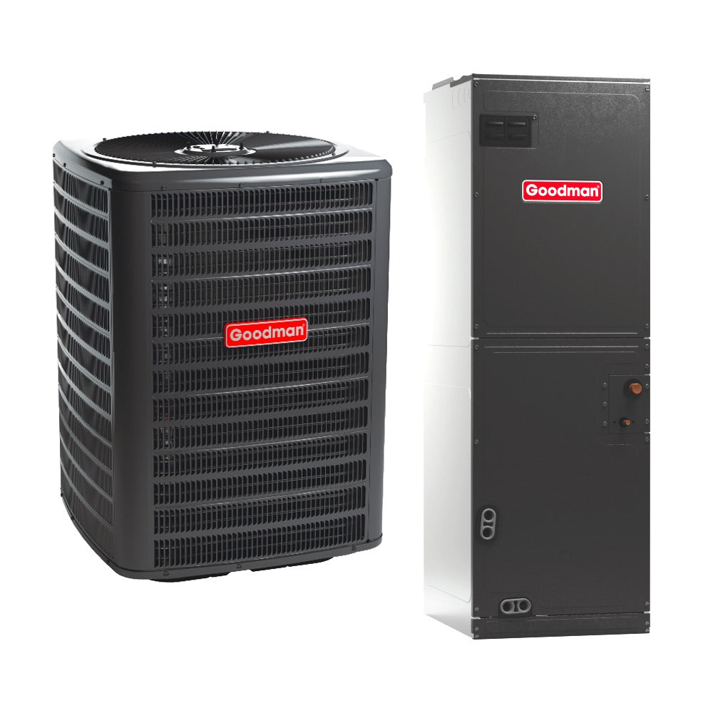
Cold-climate heat pumps now deliver solid capacity at low temps; pair with a right-sized gas furnace for dual fuel.
-
Zoned ductless for bonus rooms or additions reduces whole-home load and runtime on the main furnace.
-
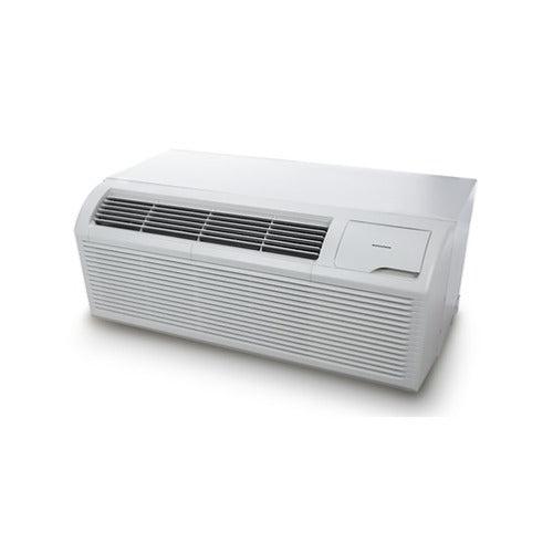
Packaged units can simplify rooftop or tight mechanical spaces.
Browse:
Even with electric options, verify branch circuit and defrost strategy at your site’s design temp and elevation.
Altitude derating reference card (printable)
Altitude (ft) Derate Effective BTU
0 0% 1.00 × Nameplate
2,500 10% 0.90 × Nameplate
4,500 18% 0.82 × Nameplate
6,000 24% 0.76 × Nameplate
7,500 30% 0.70 × Nameplate
9,000 36% 0.64 × Nameplate
10,000 40% 0.60 × Nameplate
Formula: Effective = Nameplate × (1 − 0.04 × kft)
Keep this in your truck. Always cross-check with the manufacturer’s altitude kit and utility BTU/ft³ before finalizing input.
Resources: Help Center
Final checklist before you leave the site
-
Orifices installed per altitude chart
-
Manifold pressure set and input clocked
-
Combustion verified (O₂ / CO₂ / CO air-free / stack temp)
-
Pressure switch model matches altitude; proves properly
-
Temp rise within plate; fan speed adjusted
-
Venting and condensate confirmed for elevation and run length
-
Documentation completed; homeowner briefed on filters & CO alarms
Attach a QR code linking to your job packet or the homeowner’s Help Center article for quick reference.

