From “rules of thumb” to code-mandated math
IECC 2024 codifies sizing per Manual S using building loads from Manual J (referenced in IRC M1401.3). That means no more sizing to square-foot heuristics or “matching what’s there.” Loads must reflect envelope, fenestration, orientation, climate bin data, occupancy, appliances, and internal moisture. The payoff is equipment that actually runs in its design envelope—longer cycles, tighter RH, and fewer comfort complaints.
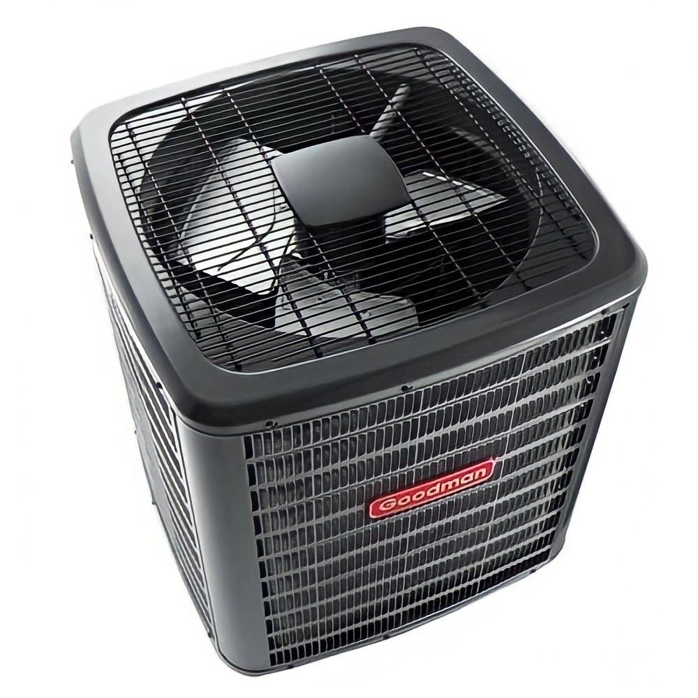
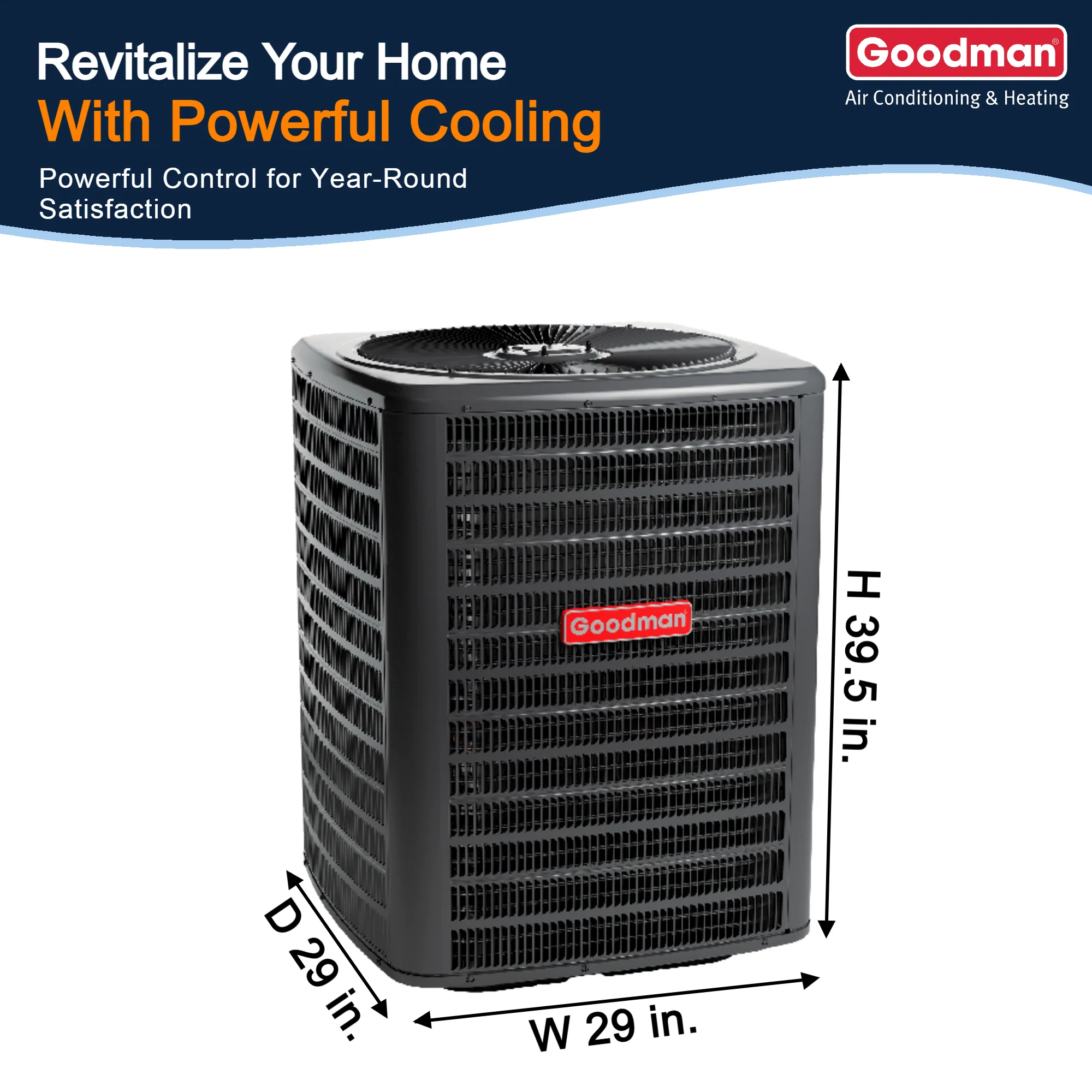
When you replace legacy 10 SEER equipment with today’s variable capacity, expect smaller tonnage after air sealing and window upgrades. For homeowners, start with our plain-English Sizing Guide and the Design Center for a compliant path.
Mandatory load calcs that survive plan review
Manual J is now the ANSI-recognized baseline for residential loads. Most jurisdictions want ACCA-approved software submittals (e.g., Elite RHVAC, Wrightsoft, Cool Calc) and enforce IECC documentation. Expect reviewers to check: design temperatures used, window/door schedules, insulation R-values, infiltration entry, duct location, and internal gains.
flowchart LR
Data[Plans & specs] --> J[Manual J Loads]
J --> S[Manual S Equipment Selection]
S --> D[Manual D Duct Design]
D --> QA[Leakage & Balancing QA]
QA --> AsBuilt[As-built Verification]
Tight envelopes, lower loads, smaller systems
IECC 2024 tightens blower-door thresholds: ≤4.0 ACH50 in warm zones and down to 2.5 ACH50 in colder zones. Add credits for <1.0 ACH50 plus ERV, and the latent profile changes dramatically. Smaller infiltration means lower sensible peaks and higher RH risk if equipment is oversized. This is where Manual J’s latent math and Manual S selection prevent clammy summers.
If a remodel pushes ducts inside the envelope (conditioned basement, soffits, dropped ceilings), your gains can justify stepping from a 3-ton to a 2-ton variable heat pump think modern ductless wall mounts.
Manual S guardrails that stop oversizing
Manual S caps equipment selection relative to the Manual J load to keep humidity control and cycling in check. Typical bounds:
-
Cooling AC: 95–115% of total load (sensible + latent)
-
Heat pumps (cooling mode): 100–125% of total cooling load
-
Heating equipment: up to ~140% of peak heating load (account for defrost/aux)
-
Variable capacity: may allow up to ~130% because of modulation
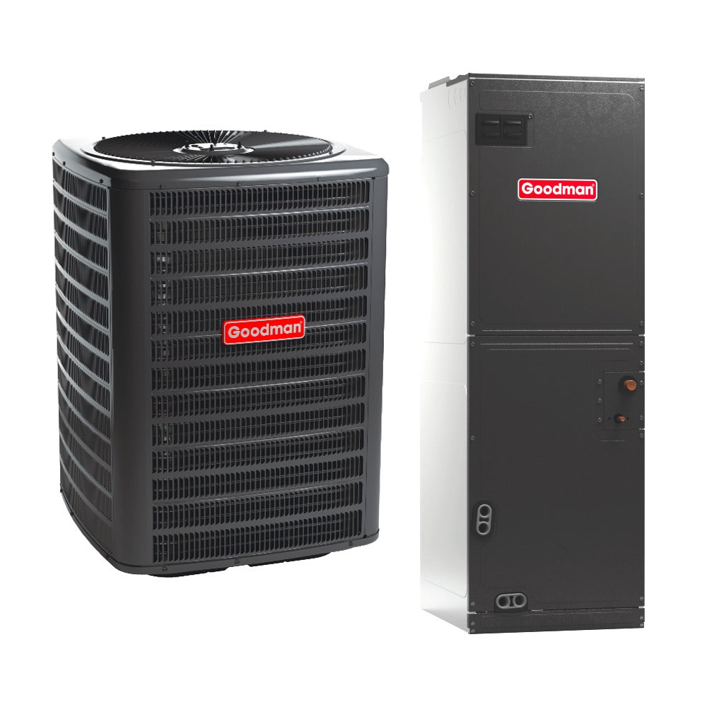
Validate sensible capacity at your design dry-bulb and indoor WB. A “3-ton” nameplate at 95°F/75°F DB/WB doesn’t guarantee 3 tons at your 97°F / 75°F indoor design. Cross-check with AHRI data and fan CFM settings. Then pick the matched set from our R-32 condensers and air handlers.
Variable capacity & heat pumps earn credits—and flexibility
IECC explicitly recognizes multi-stage and variable-speed equipment. With better part-load efficiency and moisture control, they fit Manual S allowances while scoring energy credits. Cold-climate heat pumps (high HSPF2, solid low-ambient capacity) open electrification paths where gas is costly or unavailable.
Manual D, duct leakage, and ducts-in-space
IECC 2024 tightens duct leakage; expect targets as low as 1.75 CFM25/ft² for systems without air handlers. Putting 80–100% of ducts inside conditioned space earns credits and preserves delivered BTUs. Manual D requires proper friction rate, trunk/branch sizing, equivalent length accounting, and balancing.
Field visual:
Air Handler → Trunk → Branches → Diffusers
| | | |
Filter Fittings Dampers Return paths sized by Manual D
-
Use a measured external static (ESP) and fan table to set airflow; don’t guess.
-
Seal with mastic; test with a calibrated fan.
-
Match coil/handler to condenser from our air handlers.
Standardized design temps prevent “creative” loads
IECC sets interior design temperatures: ≤72°F heating and ≥75°F cooling. This normalizes calcs across designers and blocks inflated tonnage. Always document outdoor design (ASHRAE or local) and humidity assumptions; latent control depends on indoor dry-bulb + wet-bulb pairing.
Where infiltration is ultra-low (e.g., <1.0 ACH50 with ERV), plan for reheat or dehumidify mode on shoulder days. Variable-speed mini-splits with dry mode can be decisive.
Software, documentation, and passing inspections
Jurisdictions increasingly require ACCA-approved software outputs with the “Powered by ACCA Manual J” mark plus Manual S selection sheets and Manual D duct layouts. Package your submittal as: cover page, load report, room-by-room CFM schedule, equipment selection (AHRI match), duct plan, and test plan (blower door, duct leakage).
Workflow:
-
Preliminary Manual J with the architect/specs
-
Iterate on glazing/U-factors and duct location to earn IECC credits
-
Final Manual D with fittings and balancing dampers
Use our Design Center for selection help, and attach product cutsheets from The Furnace Outlet to your permit packet.